Securing Acme Corp's AWS Traffic Flows with FortiGate NGFW

Acme Corp is migrating on prem apps/workloads to AWS Public cloud

  • 3 tier web apps (Front end, middleware, database)
Tip

CISO’s typically have the following concerns and requirements when migrating applications & workloads to public cloud.

In this workshop you will learn how FortiGates can address the following:

  • Concerns:
    • Exposure to Inbound Internet attacks
    • Environment and App segmentation to reduce exploit blast radius
    • NGFW protection & URL filtering for outbound web traffic
    • Simple security policy across Corporate Cyber Infrastructure
  • Corporate Requirements:
    • Regional HA architecture (multi AZ)
    • Traffic Protection with NGFW featuring FortiGate FortiGuard advanced protection
    • Log of all traffic (blocked and allowed)

Workshop Goals

In this workshop you will learn how to use FortiGate NGFW deployed as AWS EC2 instances to protect traffic flows in common AWS architecture patterns as well as some fundamental AWS networking concepts.

The intent is to help clarify the following:

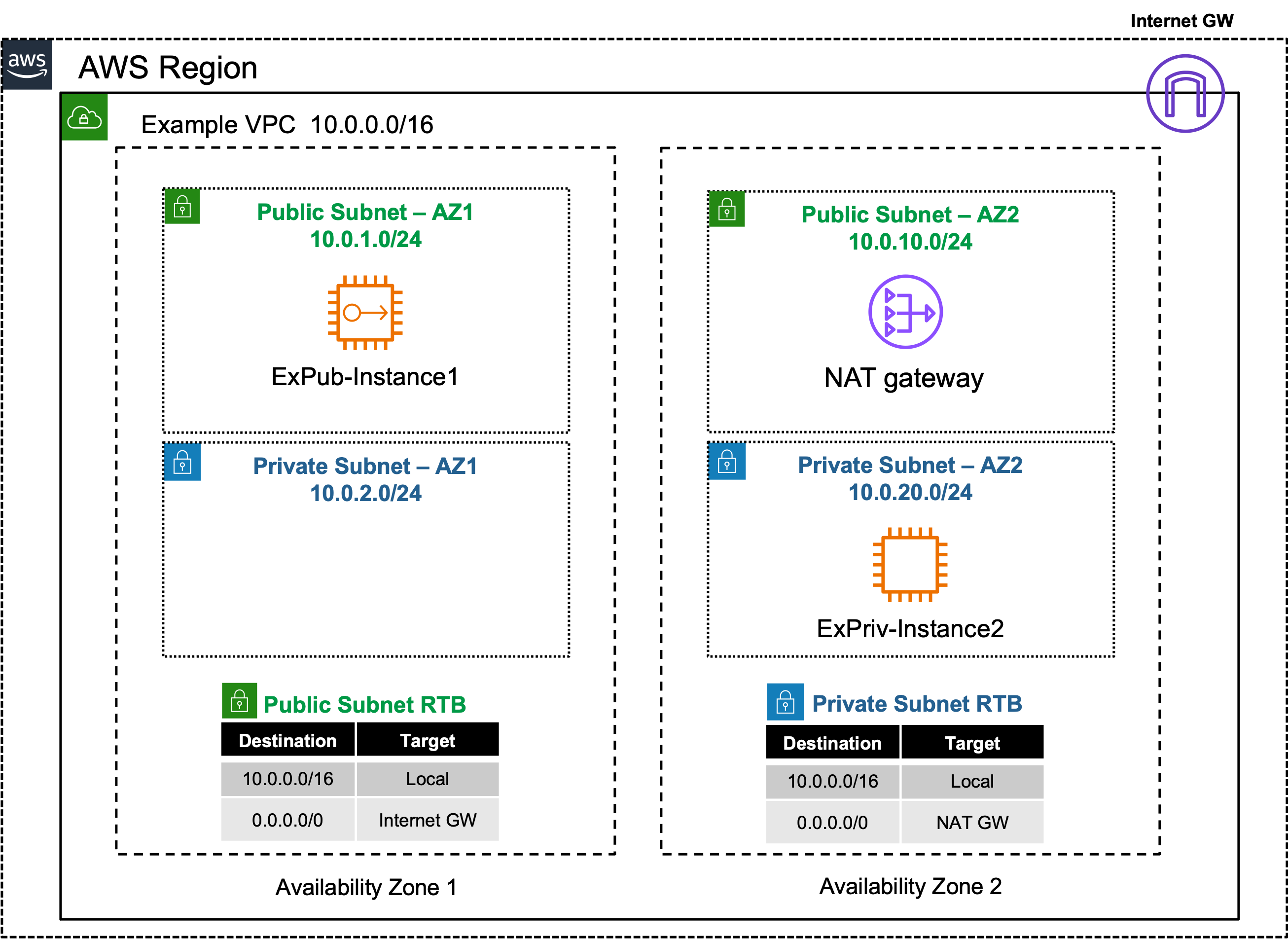
  • Learn foundational AWS networking concepts such as symmetrical routing traffic in and out of VPCs for various traffic flows
  • Use FortiGate instances in AWS to secure inbound, outbound, and East/West traffic flows
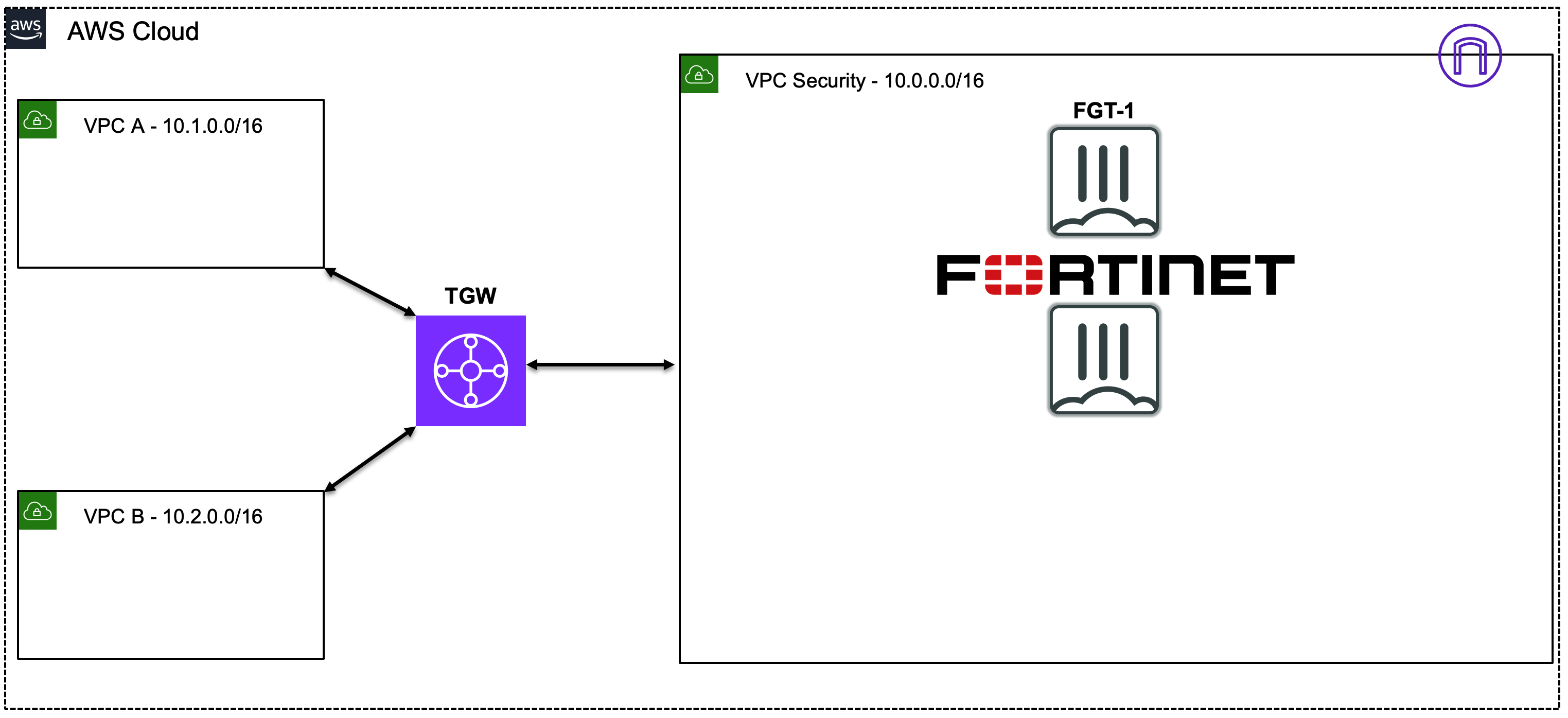
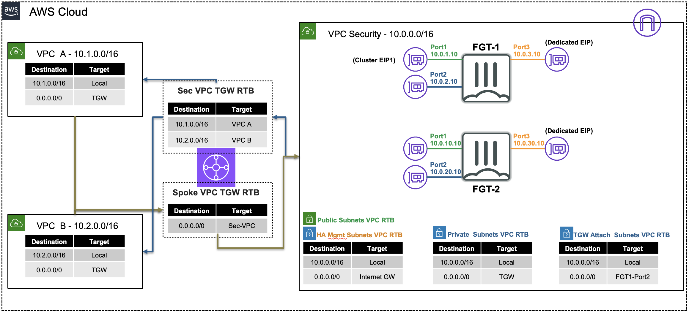
  • Introduction to FortiGate Security VPC (AWS centralized architecture) with Transit Gateway
Version:
Last updated: Thu, May 22, 2025 22:18:30 UTC
Copyright© 2025 Fortinet, Inc. All rights reserved. Fortinet®, FortiGate®, FortiCare® and FortiGuard®, and certain other marks are registered trademarks of Fortinet, Inc., and other Fortinet names herein may also be registered and/or common law trademarks of Fortinet. All other product or company names may be trademarks of their respective owners. Performance and other metrics contained herein were attained in internal lab tests under ideal conditions, and actual performance and other results may vary. Network variables, different network environments and other conditions may affect performance results. Nothing herein represents any binding commitment by Fortinet, and Fortinet disclaims all warranties, whether express or implied, except to the extent Fortinet enters a binding written contract, signed by Fortinet’s General Counsel, with a purchaser that expressly warrants that the identified product will perform according to certain expressly-identified performance metrics and, in such event, only the specific performance metrics expressly identified in such binding written contract shall be binding on Fortinet. For absolute clarity, any such warranty will be limited to performance in the same ideal conditions as in Fortinet’s internal lab tests. Fortinet disclaims in full any covenants, representations, and guarantees pursuant hereto, whether express or implied. Fortinet reserves the right to change, modify, transfer, or otherwise revise this publication without notice, and the most current version of the publication shall be applicable.

Subsections of Securing Acme Corp's AWS Traffic Flows with FortiGate NGFW

Introduction

FortiGate: Protecting AWS Traffic Flows

Learning Objectives

Upon completion of this workshop, you will gain understanding of the following objectives:

  • AWS Networking Concepts (10 minutes)
  • AWS Common Architecture Patterns (10 minutes)
  • FortiGate FortiOS terminology (10 minutes)
  • Creating & applying Firewall policies with security profiles & objects to control traffic flows (10 minutes)
  • Testing traffic flows to validate the implemented networking and security controls (20 minutes)

Workshop Components

Fortinet & AWS components used during this workshop:

  • FortiGate Instances running FortiOS (AMI on EC2)
  • AWS EC2 Instances (Amazon Linux OS, as sample workloads)
  • AWS Networking Components:
    • VPCs
    • Subnets
    • Route Tables (RTBs)
    • Transit Gateway (TGW)

AWS Reference Architecture Diagram

  • AWS networking offers multiple ways to organize your AWS architecture to take advantage of FortiGate traffic inspection. Most importantly, traffic must follow a symmetrical routing path (for forward and reverse flows). As long as flows are symmetrical, the architecture will work and traffic will flow through FortiGate NGFW for inspection.
  • We will investigate the configuration of the different architecture patterns below:
    • Ingress + Egress in a single VPC
    • Centralized Inspection of Ingress + Egress + East/West with multiple VPCs

Workshop QuickStart & FAQ

Here are a few items to help you get started on this workshop

Subsections of Workshop QuickStart & FAQ

Workshop Logistics

LaunchDemoForm

Warning

After submitting, this page will return with a blank email address box and no other indications. \*\*\* __PLEASE DO NOT SUBMIT MULTIPLE TIMES__ \*\*\*

Accessing QwikLabs & AWS environment

Fortinet Cloud Workshops, will use QwikLabs to provide a pre-staged AWS account with the workshop environment.

  • Upon login, click Dashboard (top of page).
  • Look for FortiGate: Protecting AWS Resources.
  • Click the green Start Lab button to begin.
Warning

Provisioning the lab takes ~15 minutes once started. This environment will run for 3 hours and then automatically shutdown and delete all resources. If you restart the lab, then you will start with a clean environment where you will start from the beginning again.

Once the environment has finished provisioning, check the QwikLabs Console left menu to find FortiGate NGFW & AWS console login URL and credentials .

AWS Networking Concepts

AWS Network Routing

  • AWS networking is Software Defined Networking where VPCs have a built-in or implicit router
  • VPC Route Tables (RT) are similar to static routes in traditional routing
    • Generally they are attached to a subnet impacting the destination routing decisions for that subnet only
    • Putting the pieces together, AWS routing decisions happen at every hop along the traffic path
      Tip

      Symmetrical paths are the most important rule for AWS routing

      • Traffic must follow the same path in the outbound and inbound direction
    • Sometimes RT can be associated with services (like IGW) allowing special routing decisions in specific scenarios
  • Every VPC has a default RT which allows communication between all subnets in the VPC
    • Every newly created subnet is associated with this default RT
    • you cannot change the VPC CIDR route entry in the default RT
    • You can add more specific subnet routes to a RT to do things like FortiGate NGFW Inspection of traffic BETWEEN Subnets in a VPC

AWS Networking Services

Before diving into the reference architecture for this workshop, let’s review core AWS networking concepts. Click the hyperlinks for AWS documentation.

Service NameDefined byLimitationsAffinity
VPCCIDR block (can add multiple CIDR blocks)CIDR block between /16 and /28lives in 1 region
RegionLarge geographical areaisolated from other regions (which can be connected with TGW)can have many VPCs
Availability Zonegenerally 1 physical datacenter/MANpower, cooling, and networking are shared in an AZeach region has multiple AZ’s
SubnetIP subnet of the VPC’s CIDR definitionCIDR block between /16 and /28belongs to 1 VPC and 1 AZ only
IGWVPC Route Tables (RTBs) can be associated to IGW to influence routing beyond subnet (advanced scenario)belongs to 1 VPC
NATGW1 (or more) EIPsoutbound traffic onlybelongs to 1 subnet(AZ)
EIPsingle Public IP addressbelongs to a regionattachment to EC2, NLB/ALB, NATGW
VPC Peeringpeering connection specifying 2 VPCs onlyno transitive routingrouting path between 2 VPCs only (legacy)
TGWTGW routing tables, VPC, VPN, DXC and other attachments5,000 attachments per transit gatewaybelongs to 1 region

AWS Networking Base Services

  • Virtual Private Cloud (VPC) is a logically isolated section of the AWS Cloud where you can launch AWS resources in a virtual network that you define. You have complete control over your virtual networking environment, including selection of your own IP address range, creation of subnets, and configuration of route tables and network gateways.

  • Region is a collection of multiple Availability Zones in a geographic location. The collection of AZs in the same region are all interconnected via redundant, ultra-low-latency networks.

  • Availability Zones (AZ) are multiple, isolated datacenter locations within each Region that have independent power, cooling, physical security, etc. A VPC spans all of the AZs in the Region.

  • All subnets within a VPC are able to reach each other with the default or intrinsic router within the VPC. All resources in a subnet use the intrinsic router (1st host IP in each subnet) as the default gateway. Each subnet must be associated with a VPC route table, which specifies the allowed routes for outbound traffic leaving the subnet. Subnets are tied to a single AZ.

  • Internet Gateway (IGW) is a horizontally scaled, redundant, and highly available VPC component that allows communication between instances in your VPC and the internet. It therefore imposes no availability risks or bandwidth constraints on your network traffic.

  • Elastic IP (EIP) is a static IPv4 address designed for dynamic cloud computing within a region. Simply allocate one to a region in your account and associate this to an EC2 instance to access it over the public internet.NAT Gateway (NAT GW) is a Network Address Translation (NAT) service. You can use a NAT gateway so that instances in a private subnet can connect to services outside your VPC but external services cannot initiate a connection with those instances.

AWS Network Connectivity Services

  • VPC Peering is a private and point to point connection between two VPCs. While you can connect many VPCs together in the same region, VPC peering does not support transitive routing. In the diagram below, VPC A has peering connections to both VPC B & C, so A can talk to B or C. However, VPC B can’t talk to VPC C, and the reverse as well, unless you setup a VPC peering connection directly between them. As VPCs scale, it is better to use Transit Gateway instead.
  • Transit Gateway (TGW) is a highly scalable cloud router that connects your VPCs in the same region to each other, to on-premise networks, and even to the internet through one hub. With the use of multiple route tables for a single TGW, you can design hub and spoke routing for traffic inspection and enforcement of security policy across multiple VPCs. As the name implies, Transit Gateway supports transitive routing.

AWS Data transfer cost considerations

Below is a simplified description of the most basic AWS networking & data transfer charges. The listed costs are examples only and change frequently based on the region in use. Please consult AWS documentation for costs of your specific scenario

Note

Any specific pricing listed below is for estimation purposes only. Please reference the AWS Cost Calculator for the most up-to-date pricing for your infrastructure.

Tip

Workshop participants running this workshop during a Fortinet event will not incur any AWS charges.

Transfer descriptioncost ($)
Inbound (from Internet)$0.00 (Free)
Outbound (to Internet)$0.09/GB (volume discounts apply)
Within an AZ$0.00 (Free)
Across AZs (within Region)$0.01/GB
Across Regions$0.01-0.02/GB
AWS Service costscost ($)
VPC Peering$0.00 (Free)
TGWSee AWS TGW Pricing
IGWSee AWS VPC Pricing
NATGWSee AWS VPC Pricing
EIPSee AWS VPC Pricing

In this workshop we will use these components to highlight insertion of FortiGate NGFW into an enterprise architecture.

AWS Tips and tricks

Helpful tips when working with AWS console

  • Upon login the Console Home page is displayed.
  • Use the Search Box at the top to search for services such as EC2, VPC, etc.
  • When results appear, right click the service name to open the desired console in a new tab.
    • Multiple tabs simplifies navigation when using multiple AWS services.

General

  • Its often helpful to open each new service in its own tab. That way, you can refer back to each service independently without losing the info on your screen.
    • This trick is also useful when working in multiple regions. Just be careful you make a change in the appropriate region!
  • Search/filter within a service
    • Often, when working with AWS services, it can be confusing matching a particular item to its “owner”
      • e.g. Every Subnet and RT belongs to a single VPC.
      • Identifying a specific RT from a long list of all RT in a region can be difficult
      • You can use the filters in left-nav, or top-middle search bar to filter and narrow down the viewable items
      • In the VPC Dashboard, you can filter subnets or RT to a specific VPC to help more easily identify the one you need
  • Working in different AWS regions
    • The AWS console displays services for 1 Region only.
    • If you need to work with resources in different regions, you can open multiple browser tabs to view Service consoles in different regions
    • The example below shows VPCs in US-WEST-1(N. California) & US-East-1(N. Virginia)
    • Be careful when working between regions, ensuring you make changes to the appropriate region’s services

Workshop Hands-On Agenda

Tasks in this workshop

Subsections of Workshop Hands-On Agenda

AWS Networking

In this section, we’ll learn about Single VPC traffic flows.

Subsections of AWS Networking

Single VPC & IGW

Public Inbound: Single VPC with IGW

GoalEstablish Internet access for EC2 Public instance (inbound + outbound).
TaskAdjust the route table associations so you can ping ExPub-Instance1.
Verify task completionConfirm inbound VPC connectivity to EC2 Instance via Ping the EC2 Public instance from your laptop/workstation
Warning

There are no security controls in this example. ExPub-Instance1 can freely communicate with the Internet and anybody on the Internet can reach ExPub-Instance1.

Summarized Steps (click to expand each for details)

  1. Find the EC2 Instance Public IP and verify it’s currently inaccessible.

    Detailed Steps…
    • 1.1: In your AWS account, navigate to the EC2 Console and go to the Instances page (menu on the left).
    • 1.2: Find the ExPub-Instance1 instance, and copy the Public IP address.
    • 1.3: In your command prompt or terminal, ping the public IPv4 address of the instance.
      • This SHOULD NOT work at this point.
  2. Identify the route table and examine routes, then associate the route table to the proper subnet.

    Detailed Steps…
    • 2.1: Navigate to the VPC Console and go to the Subnets page (menu on the left).
    • 2.2: Find the Example-PublicSubnet1 subnet & Select the Route table tab.
    • 2.3: Click Edit route table association.
    • 2.4: Select the Example-PublicRouteTable and click save.
  3. Verify communication to the EC2 Instance Public IP.

    Detailed Steps…
    • 3.1: Ping the Public IP/DNS of the EC2 instance from your (workstation).
    • 3.2: Browse over HTTP to the public IP of the EC2 instance from your (workstation).
      • Now you can successfully connect to the public IPv4 address of the ExPub-Instance1 instance.
    Warning

    If you are unable to access the instance webpage, you may need to disconnect from your corporate VPN or change your Web Filter settings to allow access. An upstream proxy or web filter is blocking access.

  4. Let’s dig deeper to understand how all of this works.

    • IGW implicit NAT on EC2 EIP’s.
    Detailed Steps…
    • 4.1: In the EC2 Console go to the Instances page select the ExPub-Instance1 instance.
    • 4.2: click Connect > EC2 serial console.
      • Copy the instance ID as this will be the username and click connect.
    • 4.3: Login to the EC2 instance:
      • username: «copied Instance ID from above»
      • Password: FORTInet123!
    • 4.4: Run the command ifconfig ens5 and take note of the instance IPv4 address.
    • 4.5: Run the command curl ipinfo.io.
    Info

    The instance has the private IP 10.0.1.10/24, but is reachable by and seen as the associated public IP. This is because an Elastic IP (EIP) is a 1 to 1 NAT service provided by the AWS Internet Gateway (IGW).

    • 4.6: Run the command route -n and take note of the default route and the gateway IP for that route.
    Info

    The instance has a default route going to the private IP of 10.0.1.1. This is the AWS VPC router (aka intrinsic router), which is the first host IP in any subnet within a VPC. Reference this AWS document to learn what other IPs in a subnet are always used by AWS.

    • 4.7: The VPC route table that you assigned to the public subnet has a default route to the Internet through the AWS Internet Gateway (IGW). Also this instance has an Elastic IP (EIP), a public IP, associated to it. These AWS networking components are allowing the public in/outbound access to work successfully for this instance.

    • 4.8 Below is a step by step of the packet handling for the inbound web traffic to ExPub-Instance1.

    HopComponentDescriptionPacket
    1Internet -> IGWInbound traffic destined to the EIP is received at the IGW.x.x.x.x:src-port -> y.y.y.y:80
    2IGW -> ExPub-Instance1IGW changes the destination IP to the private IP of ExPub-Instance1. The VPC router will route traffic to ExPub-Instance1.x.x.x.x:src-port -> 10.0.1.10:80
    3ExPub-Instance1 -> 0.0.0.0/0 IGWExPub-Instance1 receives the traffic, seeing the original public source IP, and replies. This traffic is sent to the VPC router (its default gw) which routes the traffic to the IGW as configured in the Example-PublicRouteTable.10.0.1.10:80 -> x.x.x.x:dst-port
    4IGW -> InternetIGW changes the source IP to the associated EIP of ExPub-Instance1 and routes the traffic to the internet.y.y.y.y:80 -> x.x.x.x:dst-port

Discussion Points

  • EC2 instances can be assigned an EIP for public reachability.
  • VPC’s must have an IGW associated to provide Internet access to any subnet in the VPC.
  • Subnets have a default RTB associated to them upon creation, allowing default reachability between all subnets in the VPC.
  • You can create additional RTBs within a VPC, and then associate each RTB to one or more subnets, altering the routing behavior of ALL TRAFFIC within that subnet.
  • This is a very basic setup and is often used as a “hello world” demo for intro to cloud.
    • Without any additional actions taken, this EC2 instance is wide open to the Internet, meaning it can communicate freely to anywhere on the Internet and anybody on the Internet can communicate freely to it. As we’ll see later, there are already inbound probing attempts against this instance even though it was just launched in the last 30 minutes.

This concludes this task

Single VPC & NATGW

Private Outbound: Single VPC with NATGW

GoalEstablish outbound only Internet access for EC2 Private instance.
TaskAdjust the route table associations so ExPriv-Instance1 can reach the Internet.
Verify task completionConfirm outbound VPC connectivity from EC2 Instance via Ping to Internet from the EC2 instance
Warning

There are no security controls in this example. However, NATGW is a 1-way service, only allowing connectivity outbound. While ExPriv-Instance2 can freely browse the Internet (outbound), no Internet hosts can connect to it (inbound).

Summarized Steps (click to expand each for details)

  1. Login to ExPriv-Instance2 and verify it cannot access the Internet.

    Detailed Steps…
    • 1.1: In the EC2 Console go to the Instances page (menu on the left) and select the ExPriv-Instance2 instance.
    • 1.2: click Connect > EC2 serial console.
      • Copy the instance ID as this will be the username and click connect.
    • 1.3: Login to the EC2 instance:
      • username: «copied Instance ID from above»
      • Password: FORTInet123!
    • 1.4: Run the command ping -c5 8.8.8.8 to connect to public resources.
      • This SHOULD NOT work at this point.
  2. Identify the relevant route table and add the proper route so 0.0.0.0/0 traffic is sent to NATGW.

    Detailed Steps…
    • 2.1: Navigate to the VPC Console and go to the Subnets page (menu on the left).
    • 2.2: Find the Example-PrivateSubnet2 subnet.
    • 2.3: Select the Route table tab and click the actual route table name rtb-…. / Example-PrivateRouteTable.
    • 2.4: Select the Example-PublicRouteTable then select the Routes tab and click Edit routes.
    • 2.5: Add a default route (ie 0.0.0.0/0) with a target of the NAT Gateway and click Save changes.
  3. Test Internet connectivity from ExPriv-Instance2 again.

    Detailed Steps…
    • 3.1: Go back to the EC2 serial console and rerun the command ping -c5 8.8.8.8 to connect to public resources successfully.
  4. Let’s dig deeper to understand how all of this works.

    Detailed Steps…
    • 4.1: Run the command ifconfig ens5 and take note of the instance IPv4 address.
    • 4.2: Run the command curl ipinfo.io.
    Info

    The instance has the private IP 10.0.20.10/24, but is and seen as coming from a public IP. This is because a NAT Gateway is providing outbound access to the internet for this private EC2 instance.

    • 4.3: In the VPC Console go to the NAT gateways page (menu on the left).

    • 4.4: Find the Example-NatGW NAT Gateway and notice the public IP from the curl output matches the primary public IPv4 address assigned to NATGW.

      • The NAT Gateway is deployed in the Example-PublicSubnet2 subnet which has a route to the Internet through the AWS Internet Gateway (IGW).

      • These AWS Networking components are allowing private outbound access to work successfully for this instance.

    • 4.5 Below is a step by step of the packet handling for the outbound web traffic from ExPriv-Instance2.

    HopComponentDescriptionPacket
    1ExPriv-Instance2 -> 0.0.0.0/0 NAT GWExPriv-Instance2 sends outbound traffic to the VPC router (it’s default gw) which routes the traffic to NAT GW as configured in the Example-PrivateRouteTable.10.0.2.10:src-port -> x.x.x.x:80
    2NAT GW -> 0.0.0.0/0 IGWNAT GW changes the source IP to its own private IP and sends the traffic to VPC router. The VPC router routes traffic to IGW as configured in the Example-PublicRouteTable.y.y.y.y:src-port -> x.x.x.x:80
    3IGW -> InternetIGW changes the source IP to the associated EIP of NAT GW and routes the traffic to the internet.z.z.z.z:src-port -> x.x.x.x:80
    4Internet -> IGWIGW receives reply traffic, changes the source IP to the private IP of NAT GW, and sends the traffic to VPC router. The VPC router routes traffic to the NAT GW.x.x.x.x:80 -> y.y.y.y:dst-port
    5NAT GW -> ExPriv-Instance2NAT GW changes the source IP back to the private IP of ExPriv-Instance2 and routes the traffic to the VPC router which delivers the traffic to ExPriv-Instance2.x.x.x.x:80 -> 10.0.2.10:dst-port

Discussion Points

  • NAT GW providing many to 1 NAT, for outbound only.
  • No internal reachability via NATGW, so no inbound probes seen on any of the private instances.
  • General best practice, though thoroughly insufficient for overall security principles.

This concludes this task

Securing Flows with FortiGate

Adding Security for traffic flows

In this section we’ll work with a FortiGate Secured Centralized VPC and Transit Gateway connectivity

Subsections of Securing Flows with FortiGate

FortiGate Secured In/Outbound

FortiGate Security VPC in Centralized Architecture with TGW

GoalUtilize the provisioned Security VPC and Transit gateway architecture to provide security for inbound flows with FortiGate NGFW.
TaskCreate FortiGate VIP and Policy rule allowing inbound traffic to web servers.
Verify task completionConfirm inbound VPC connectivity from Internet via Browser session to FortiGate VM from your laptop/workstation

Summarized Steps (click to expand each for details)

  1. Login for FortiGate GUI and add a VIP.

    Detailed Steps…
    • 1.1: Login to the FortiGate GUI, using the Fgt outputs in the QwikLabs Console.
      • The fgtclusterurl, fgtuser, and fgtpassword outputs will be available on the left side of the Qwiklabs console.
    • 1.2: Upon login, navigate to Network > Static Routes.
    • 1.3: Edit the existing route to 10.0.0.0/16.
      • This route needs to be updated to allow access to both the Spoke VPCs that are part of this centralized design. Change the destination to 10.0.0.0/8 and click OK to save the change.

    • 1.4: Navigate to Policy & Objects > Virtual IPs, and click Create new.
    • 1.5: Create a VIP with the settings shown below and click OK.

  2. Add a Firewall Policy allowing inbound traffic to the newly created VIP.

    Detailed Steps…
    • 2.1: Navigate to Policy & Objects > Firewall Policy and click Use new layout when prompted, then click Create new.
    Tip

    If you accidentally did not use the new layout, you can change it by clicking on Classic Layout in the top right and switch to Use new layout.

    • 2.2: Create a new policy with the settings shown below and click OK to allow inbound HTTP to Spoke1-Instance1.
    Tip

    Please make sure to disable NAT so the web server can see your public IP instead of a private IP of the primary FortiGate.

  3. Test the newly created VIP & policy.

    Detailed Steps…
    • 3.1: Open a new browser tab on your workstation and browse to http://FgtClusterLoginURL.
      • You should see a web page showing details about Spoke1-Instance1.
      • If NAT was disabled, you should see your public IP on the web page.
    Warning

    If you are unable to access the instance webpage, you may need to disconnect from your corporate VPN or change your Web Filter settings to allow access. An upstream proxy or web filter is blocking access.

  4. Let’s dig deeper to understand how all of this works.

    Detailed Steps…
    • 4.1: In the FortiGate GUI navigate to Log & Report > Forward Traffic and you should see logs for the traffic you generated.
    • 4.2: Double click a log entry to view the Log Details.
    Info

    In the Source section of the log, we see the original public IP and country/region of the client. In the Destination section, we see that the original destination is the private IP of port1 of the primary FortiGate. This is because the public IP you navigated to is an Elastic IP (EIP) which is a 1 to 1 NAT service provided by the AWS Internet Gateway (IGW). We also see the destination NAT IP is the private IP of Spoke1-Instance1 because of the VIP object that was matched.

    In the Application Control section we can see details about the browser used. Navigate to the Security tab of the Log Details and you can see detailed user agent information as well.

    • 4.3: Navigate to the EC2 Console and go to the Instances page (menu on the left).
    • 4.4: Find and select the Spoke1-Instance1 instance then click Connect > EC2 serial console.
      • Copy the instance ID as this will be the username and click connect.
    • 4.5: Login to the EC2 instance:
      • username: <<copied Instance ID from above>>
      • Password: FORTInet123!
    • 4.6: Run the commands ping -c5 8.8.8.8 and curl ipinfo.io to connect to public resources, successfully.
    • 4.7: To test downloading an EICAR test virus over HTTPS to a local file, run the command curl -k --retry 2 --retry-all-errors https://secure.eicar.org/eicar.com.txt -o file.txt.
    • 4.8: To check the content of the file, run the command cat file.txt | grep -A 15 'High Security Alert'.
      • You will see you were blocked and a block page was returned.
  5. Let’s dig deeper to understand how all of this works.

    Detailed Steps…

    • 5.1: In the FortiGate GUI navigate to Log & Report > Forward Traffic. You should logs for the traffic you generated.
    • 5.2: Double click a log entry to view the Log Details.
    Info

    The instance has the private IP 10.1.2.10/24, but is seen as coming from a public IP. This is because the primary FortiGate is providing secured outbound access to the internet for this private EC2 instance. This is because of the VPC routes in all the VPCs (Spoke1 and Security) are working together with the Transit Gateway (TGW) and Transit Gateway route tables to route the in/outbound traffic through the primary FortiGate. This is a centralized design that is also commonly called an appliance, inspection, or security VPC.

    Navigate to Policy & Objects > Firewall Policy and look at the security profiles being applied to the secured-outbound-traffic-with-nat policy. This pre-configured policy is applying source NAT to act as a NAT Gateway but is also applying advanced NGFW protection such as SSL MitM, Application Control, Intrusion Prevention, and Anti-Virus features.

    • 5.3 Below is a step by step of the packet handling for the outbound web traffic from Spoke1-Instance1.
    HopComponentDescriptionPacket
    1Spoke1-Instance1 -> 0.0.0.0/0 TGWSpoke1-Instance1 sends outbound traffic to the VPC router (its default gw) which routes traffic to TGW as configured in the Spoke1 VPC RTB.10.1.2.10:src-port -> x.x.x.x:80
    2Spoke1-TGW-Attachment -> 0.0.0.0/0 Sec-TGW-AttachmentSpoke1-TGW-attachment is associated to the Spoke VPC TGW RTB. This TGW RTB has a default route to Sec-TGW-Attachment, so traffic is forwarded there.10.1.2.10:src-port -> x.x.x.x:80
    3Sec-TGW-Attachment -> 0.0.0.0/0 FGT1-Port2Sec-TGW-Attachment is attached to the Security VPC TGW Attach Subnets which have a default route to primary FortiGate1 Port2, private interface.10.1.2.10:src-port -> x.x.x.x:80
    4FGT1-Port1 -> 0.0.0.0/0 IGWFGT1 changes the source IP to the private IP of Port1 as this has an EIP associated. FGT1 sends inspected & allowed traffic to the VPC router via Port1 (its default gw), which routes traffic to the IGW as configured in the Public Subnet VPC RTB.10.0.1.10:src-port -> x.x.x.x:80
    5IGW -> InternetIGW changes the source IP to the associated EIP of FortiGate1 Port1 and routes traffic to the internet.z.z.z.z:src-port -> x.x.x.x:80
    6Internet -> IGWIGW receives reply traffic and changes the source IP to the private IP of FortiGate1 Port1. The VPC router routes traffic to FortiGate1 Port1.x.x.x.x:80 -> 10.0.1.10:dst-port
    7FGT1-Port2 -> 0.0.0.0/0 TGWFGT1 receives traffic on Port1, changes the source IP to the private IP of Spoke1-Instance1, and routes inspected & allowed traffic to the VPC router (10.0.0.0/8 static route out port2) via Port2. The VPC router sends traffic to TGW as configured in the Private Subnet VPC RTB.x.x.x.x:80 -> 10.1.2.10:dst-port
    8Sec-TGW-Attachment -> 10.1.0.0/16 Spoke1-TGW-AttachmentSec-TGW-Attachment is associated to the Sec VPC TGW RTB. This TGW RTB has a route for Spoke1 VPC via Spoke1-TGW-Attachment, so traffic is forwarded there.x.x.x.x:80 -> 10.1.2.10:dst-port
    9Spoke1-TGW-Attachment -> Spoke1-Instance1Spoke1-TGW-Attachment is attached to subnets in Spoke1 VPC which have a local VPC route to reach Spoke1-Instance1.x.x.x.x:80 -> 10.1.2.10:dst-port

Discussion Points

  • TGW handles inter-VPC routing for full-mesh connectivity.
  • Centralized Security VPC handles FortiGate NGFW inspection for any traffic flow (Inbound, Outbound, East/West).
    • advanced architectures for all of these scenarios can be found here.

This concludes this task

FortiGate Secured East/West

FortiGate Security VPC securing East/West Traffic

GoalUtilize the provisioned Security VPC and Transit gateway architecture to provide security for East/West (Inter-VPC) flows with FortiGate NGFW.
TaskCreate FortiGate Policy objects and rules allowing East/West traffic to Acme Corp resources.
Verify task completionConfirm east/west VPC connectivity from EC2 Instance in Spoke1 via Ping to EC2 instance in Spoke 2

Summarized Steps (click to expand each for details)

  1. Create Dynamic Address Objects.

    Detailed Steps…
    • 1.1: In the FortiGate GUI, navigate to Policy & Objects > Addresses, and click Create new.
    • 1.2: Create an address object with the settings shown below and click OK.
    Tip

    Dynamic address objects allows creating address objects based on resource metadata such as VPC ID, Auto Scale Group, EKS Cluster or Pod, and even Tag Name + Value pairs applied to the resource. FortiOS is using AWS API calls behind the scenes such as ec2:DescribeInstances, eks:ListClusters, eks:DescribeCluster, etc to find running resources to match based on metadata and pull their IP address information. This is done on a frequent basis to keep the dynamic address object up to date automatically. To learn more about all the public and private clouds this feature supports, check out our documentation.

    NameTypeSub TypeSDN ConnectorAddress TypeFilter Value
    ProdWebFrontendDynamicFabric Connector Addressaws-instance-rolePrivateTag.env=prod AND Tag.app-role=web AND Tag.app-tier=frontend
    ProdApiBackendDynamicFabric Connector Addressaws-instance-rolePrivateTag.env=prod AND Tag.app-role=api AND Tag.app-tier=backend

  2. Create Firewall Policy permitting East/West Traffic.

    Detailed Steps…
    • 2.1: Navigate to Policy & Objects > Firewall Policy and click Create new.
    • 2.2: Create a new policy with the settings shown below and click OK to allow east west traffic from Spoke1-Instance1 to Spoke2-Instance1.

    • 2.3: Validate that the dynamic address objects are automatically populated by hovering over both objects. In the popup menu, click View Matched Addresses button. ProdWebFrontend should have 10.1.2.10 and ProdApiBackend 10.2.20.10.

    • 2.4:
  3. Verify connectivity from Spoke1-Instance1.

    Detailed Steps…
    • 3.1: Navigate to the EC2 Console and go to the Instances page (menu on the left).

    • 3.2: Find & Select the Spoke1-Instance1 instance and select the Tags tab (detail pane below) to view the tags applied to the instance. Notice the tags seen here are the metadata that the FortiOS dynamic address objects are matching against. Search for app or env to see just the relevant tag key and value pairs.

    • 3.3: Find & Select the Spoke1-Instance1 instance and click Connect > EC2 serial console.

      • Copy the instance ID as this will be the username and click connect.
    • 3.4: Login to the EC2 instance:

      • username: <<copied Instance ID from above>>
      • Password: FORTInet123!
    • 3.5: Run the commands ping -c5 10.2.20.10 and curl 10.2.20.10 to connect to private resources, successfully.

    • 3.6: Run the command ssh 10.2.20.10 to be blocked by firewall policy.

  4. Let’s dig deeper to understand how all of this works.

    Detailed Steps…
    • 4.1: Navigate to Log & Report > Forward Traffic and you should logs for the traffic you generated.
    • 4.2: Double click a log entry to view the Log Details.
    Info

    In the Source and Destination sections of the log, we see the no NAT is applied and traffic comes in and goes out port2 of the Primary FortiGate. This is because of the VPC routes in the all VPCs (Spoke1, NGFW, and Spoke2) are working together with the Transit Gateway (TGW) and Transit Gateway route tables to route the east/west traffic through the primary FortiGate. This is a centralized design that is also commonly called an appliance, inspection, or security VPC.

    We can also see denied traffic that is matching the Implicit Deny firewall policy. With adding granular firewall policies & objects including dynamic address objects and security profiles, you can securely control traffic as desired.

    • 4.3 Below is a step by step of the packet handling for the east/west web traffic from Spoke1-Instance1.
    HopComponentDescriptionPacket
    1Spoke1-Instance1 -> 0.0.0.0/0 TGWSpoke1-Instance1 sends east/west traffic to the VPC router (its default gw) which routes traffic to TGW as configured in the Spoke1 VPC RTB.10.1.2.10:src-port -> 10.2.20.10:80
    2Spoke1-TGW-Attachment -> 0.0.0.0/0 Sec-TGW-AttachmentSpoke1-TGW-attachment is associated to the Spoke VPC TGW RTB. This TGW RTB has a default route to Sec-TGW-Attachment, so traffic is forwarded there.10.1.2.10:src-port -> 10.2.20.10:80
    3Sec-TGW-Attachment -> 0.0.0.0/0 FGT1-Port2Sec-TGW-Attachment is attached to the Security VPC TGW Attach Subnets which have a default route to primary FortiGate1 Port2, private interface.10.1.2.10:src-port -> 10.2.20.10:80
    4FGT1-Port2 -> 0.0.0.0/0 TGWFGT1 sends inspected & allowed traffic to the VPC router (10.0.0.0/8 static route out port2) via Port2, which routes traffic to the TGW as configured in the Private Subnet VPC RTB.10.1.2.10:src-port -> 10.2.20.10:80
    5Sec-TGW-Attachment -> 10.2.0.0/16 Spoke2-TGW-AttachmentSec-TGW-Attachment is associated to the Sec VPC TGW RTB. This TGW RTB has a route for Spoke2 VPC via Spoke2-TGW-Attachment, so traffic is forwarded there.10.1.2.10:src-port -> 10.2.20.10:80
    6Spoke2-TGW-Attachment -> Spoke2-Instance1Spoke2-TGW-Attachment is attached to subnets in Spoke2 VPC which have a local VPC route to reach Spoke2-Instance1.10.1.2.10:src-port -> 10.2.20.10:80
    7Spoke2-Instance1 -> 0.0.0.0/0 TGWSpoke2-Instance1 sends reply traffic to the VPC router (its default gw) which routes traffic to TGW as configured in the Spoke1 VPC RTB.10.2.20.10:80 -> 10.1.2.10:dst-port
    8Spoke2-TGW-Attachment -> 0.0.0.0/0 Sec-TGW-AttachmentSpoke2-TGW-attachment is associated to the Spoke VPC TGW RTB. This TGW RTB has a default route to Sec-TGW-Attachment, so traffic is forwarded there.10.2.20.10:80 -> 10.1.2.10:dst-port
    9Sec-TGW-Attachment -> 0.0.0.0/0 FGT1-Port2Sec-TGW-Attachment is attached to the Security VPC TGW Attach Subnets which have a default route to primary FortiGate1 Port2, private interface.10.2.20.10:80 -> 10.1.2.10:dst-port
    10FGT1-Port2 -> 0.0.0.0/0 TGWFGT1 sends inspected & allowed traffic to the VPC router (10.0.0.0/8 static route out port2) via Port2, which routes traffic to the TGW as configured in the Private Subnet VPC RTB.10.2.20.10:80 -> 10.1.2.10:dst-port
    11Sec-TGW-Attachment -> 10.1.0.0/16 Spoke1-TGW-AttachmentSec-TGW-Attachment is associated to the Sec VPC TGW RTB. This TGW RTB has a route for Spoke1 VPC via Spoke1-TGW-Attachment, so traffic is forwarded there.10.2.20.10:80 -> 10.1.2.10:dst-port
    12Spoke1-TGW-Attachment -> Spoke1-Instance1Spoke1-TGW-Attachment is attached to subnets in Spoke1 VPC which have a local VPC route to reach Spoke1-Instance1.10.2.20.10:80 -> 10.1.2.10:dst-port

This concludes this task