Gateway Load Balancer
| Goal | Utilize the provisioned Gateway Load Balancer architecture to provide security for distributed ingress and centralized egress flows with FortiGate NGFW. |
| Task | Create VPC routes and FortiGate Policy objects allowing both flows of traffic. |
| Validation | Confirm connectivity to Public NLB1 and from Instance-B. |
Introduction
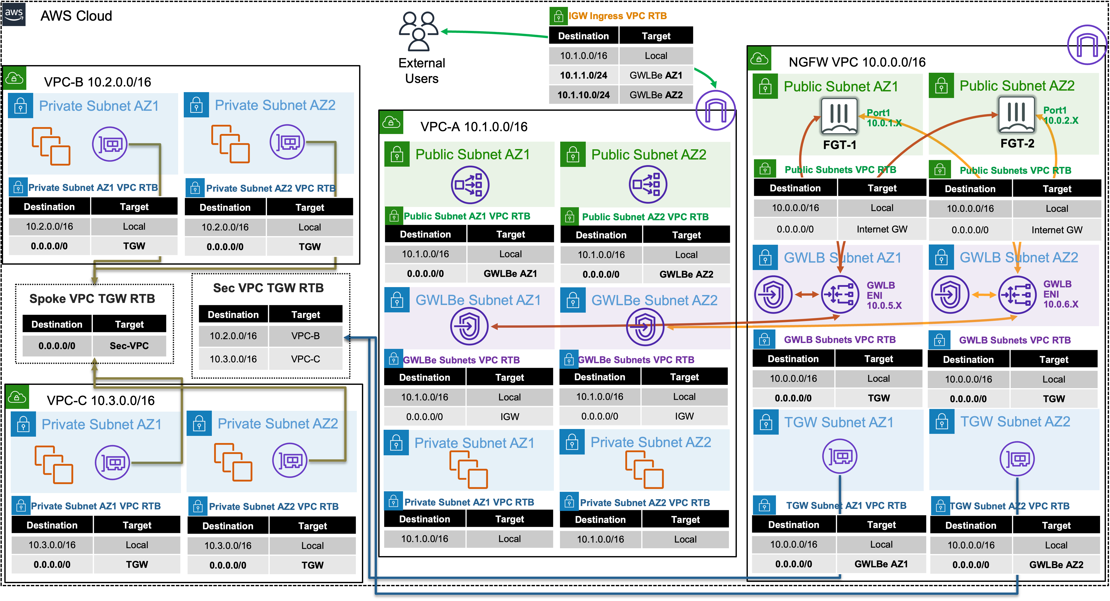
In this scenario, there are multiple VPCs in the same region that have one instance each. Transit Gateway is configured with multiple Transit Gateway Route Tables and Gateway Load Balancer and endpoints are already configured as well. You will need to create the appropriate VPC routes to redirect traffic to Gateway Load Balancer via the deployed endpoints so the Active-Active FortiGates can inspect the traffic.
In this scenario these FortiGate NGFWs are working together in an Active-Active design to provide more capacity for bump in the wire inspection. This design is usable with workload VPCs that have a direct path to/from the Internet via an attached Internet Gateway (IGW), with or without a NAT Gateway (commonly referred to a distributed design). This design can also work in conjunction with Transit Gateway to offer centralized egress, ingress, and east/west inspection (commonly referred to a centralized design).
Summarized Steps (click to expand each for details)
0) Lab environment setup
Detailed Steps…
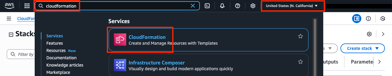
- 0.1: Login to your AWS account and navigate to the CloudFormation Console and toggle View Nested to off.
- 0.2: Make sure you are in the United States (N. California) region as this is where the stack should be deployed.
Expand for Screenshots
Info
All AWS resources for this lab will be deployed in the United States (N. California) region. Either switch the region for your existing browser tabs (using the region selector in the upper right corner of the AWS Console) to this region or close all other browser tabs. Otherwise, you might accidently configure the wrong AWS resources.
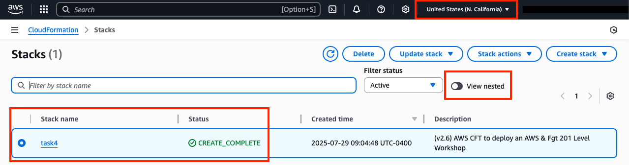
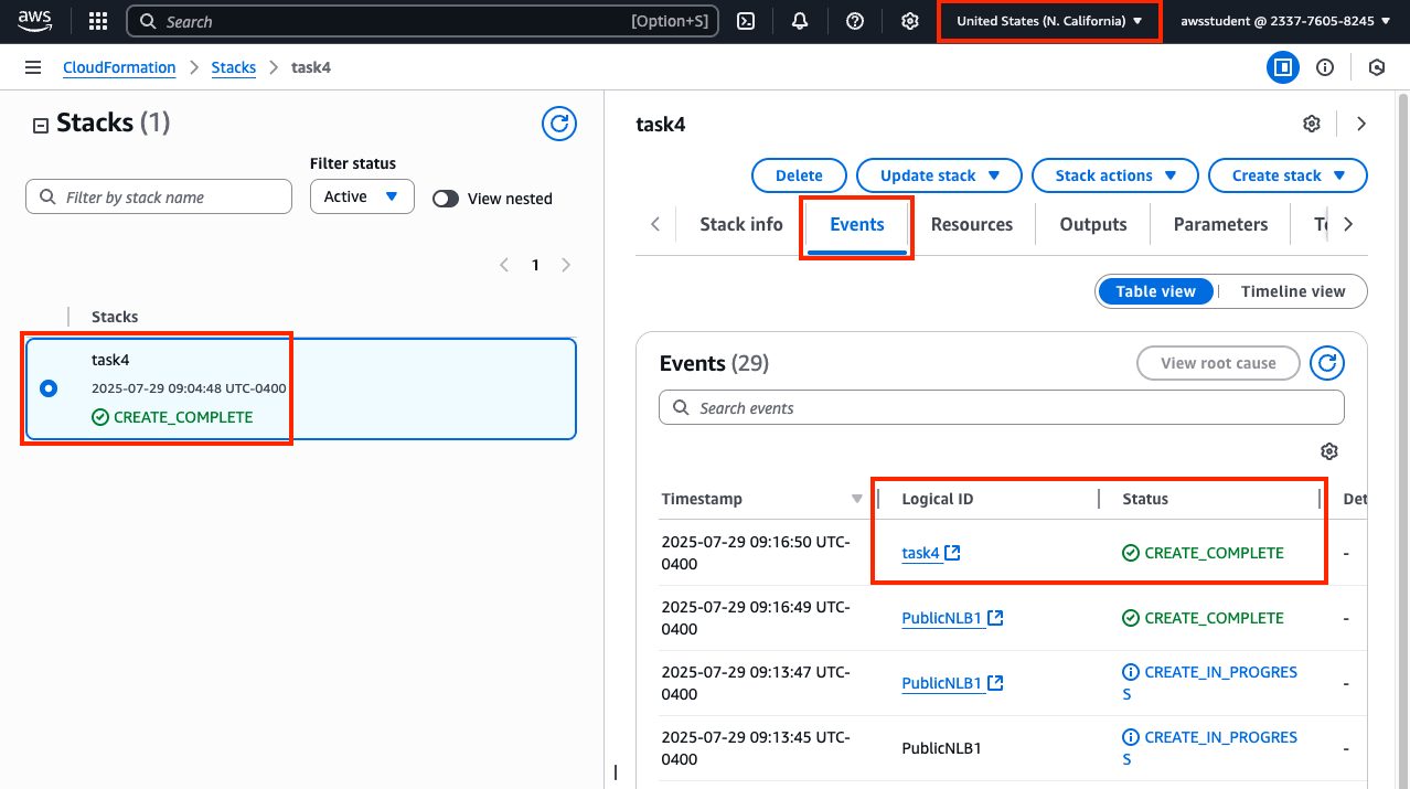
- 0.3: Select the main stack and confirm the stack has finished creating successfully by looking at the Events Tab.
Expand for Screenshot
- 0.4: You are now ready to proceed with the rest of the lab below starting in section 1. The remaining steps for this section are if the main stack failed to create successfully.
Warning
If the original stack failed to create, please notify those giving the workshop to review the root cause of the issue. Once that is done, please proceed with the remaining steps for this section.
- 0.5: Delete the previously failed main stack and wait till that has completed successfully. Please use the refresh buttons to refresh both the left and right portions of the CloudFormation Console.
- 0.6: Click the yellow Launch Stack button directly below this sentence to launch the CloudFormation Stack for Task 4

- 0.7: You must:
- select the existing IAM role
qls-...CloudFormationServiceRole...in the Permissions section - check the boxes to acknowledge the warnings in the Capabilities section
- then scroll down and click Create stack
- select the existing IAM role
Warning
If you do not select the existing IAM role and continue with the stack creation, this will fail! If this occurred, simply create another stack with a different name and follow the steps closely for this section.
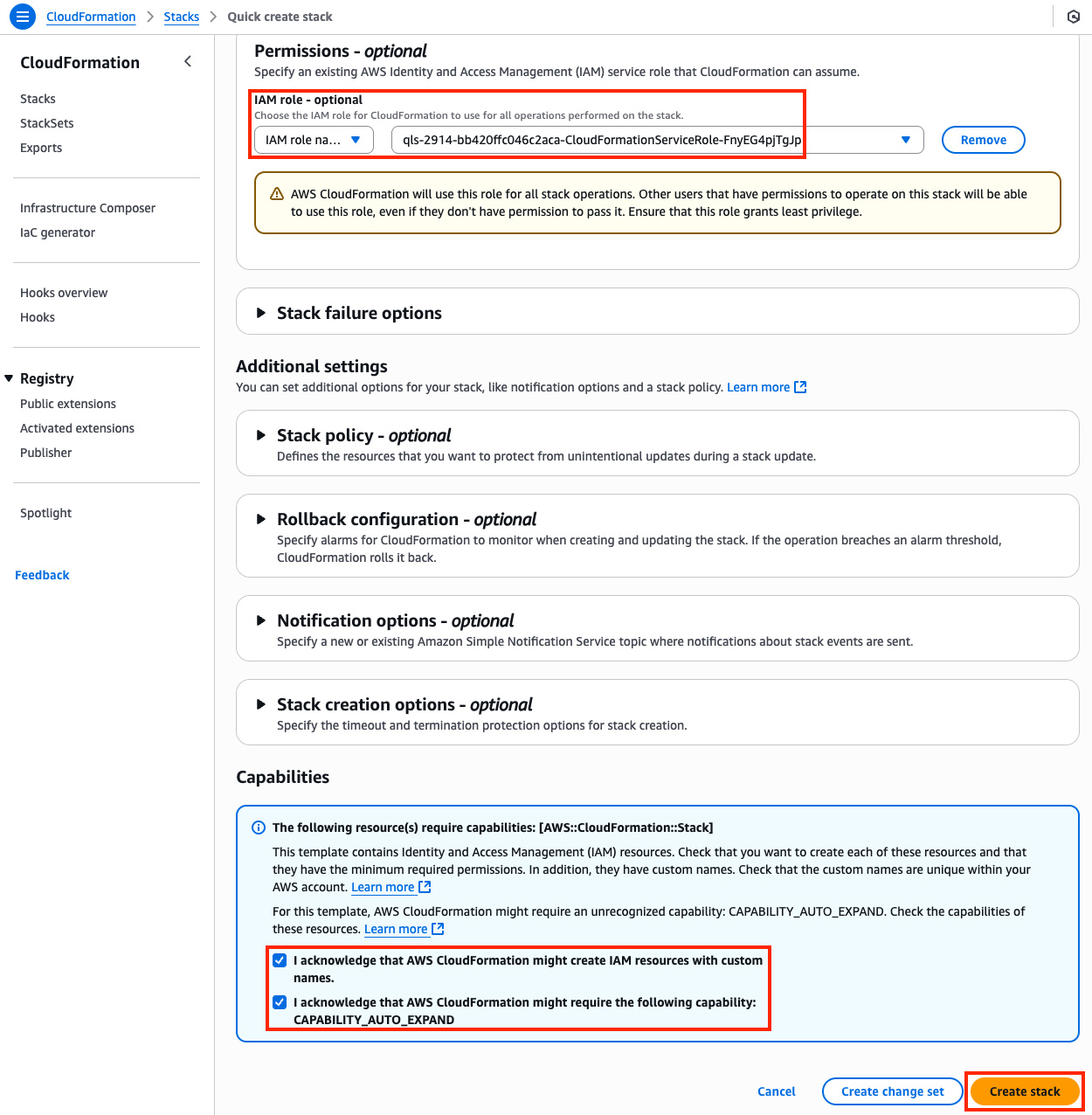
- 0.8: The CloudFormation stack will take ~12 minutes to finish deploying. Once the main/root CloudFormation stack shows as Create_Complete, proceed with the steps below.
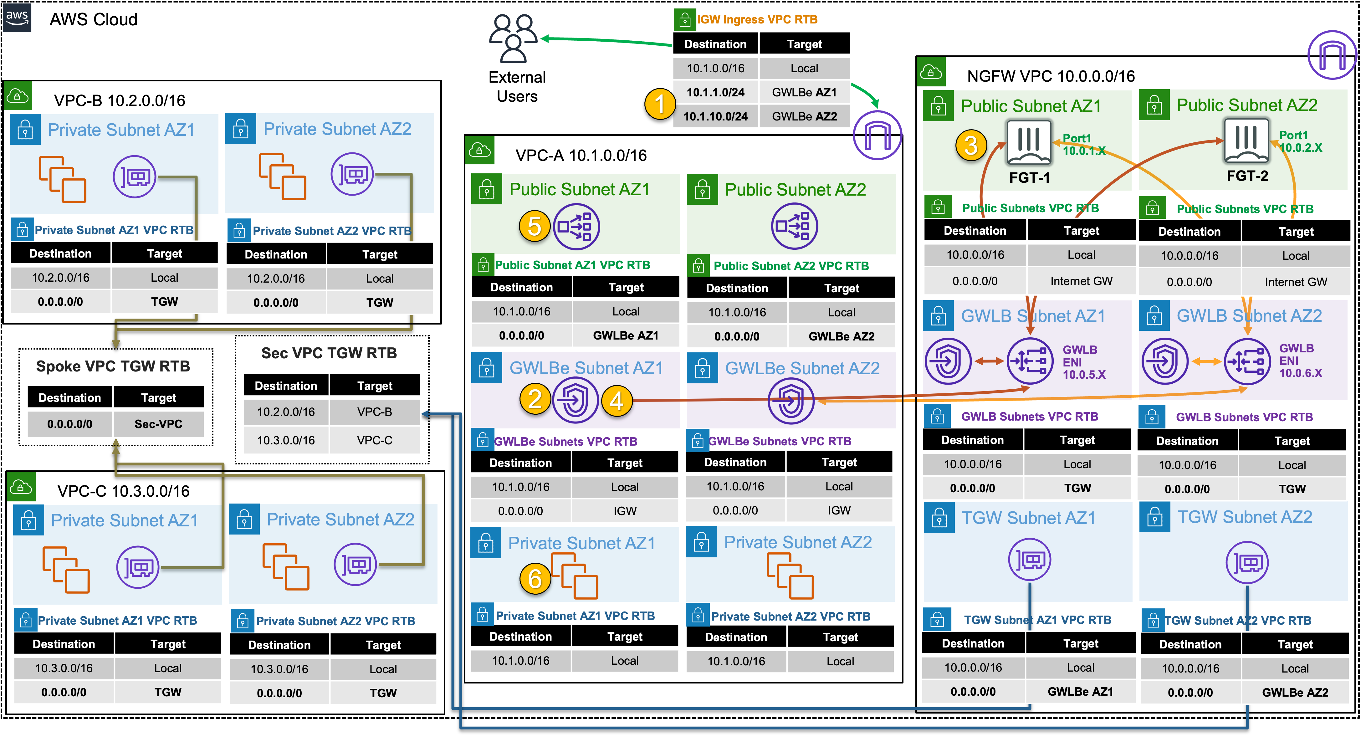
1) Create VPC routes for ingress routing
2) Create an ingress FW policy using a dynamic address object for Public NLB1 in VPC-A on both FortiGates
Detailed Steps…
- 2.1: Navigate to the CloudFormation Console and toggle View Nested to off.
- 2.2: Select the main template and select the Outputs tab.
- 2.3: Login to FortiGate1, using the outputs FGT1LoginURL, Username, and Password.
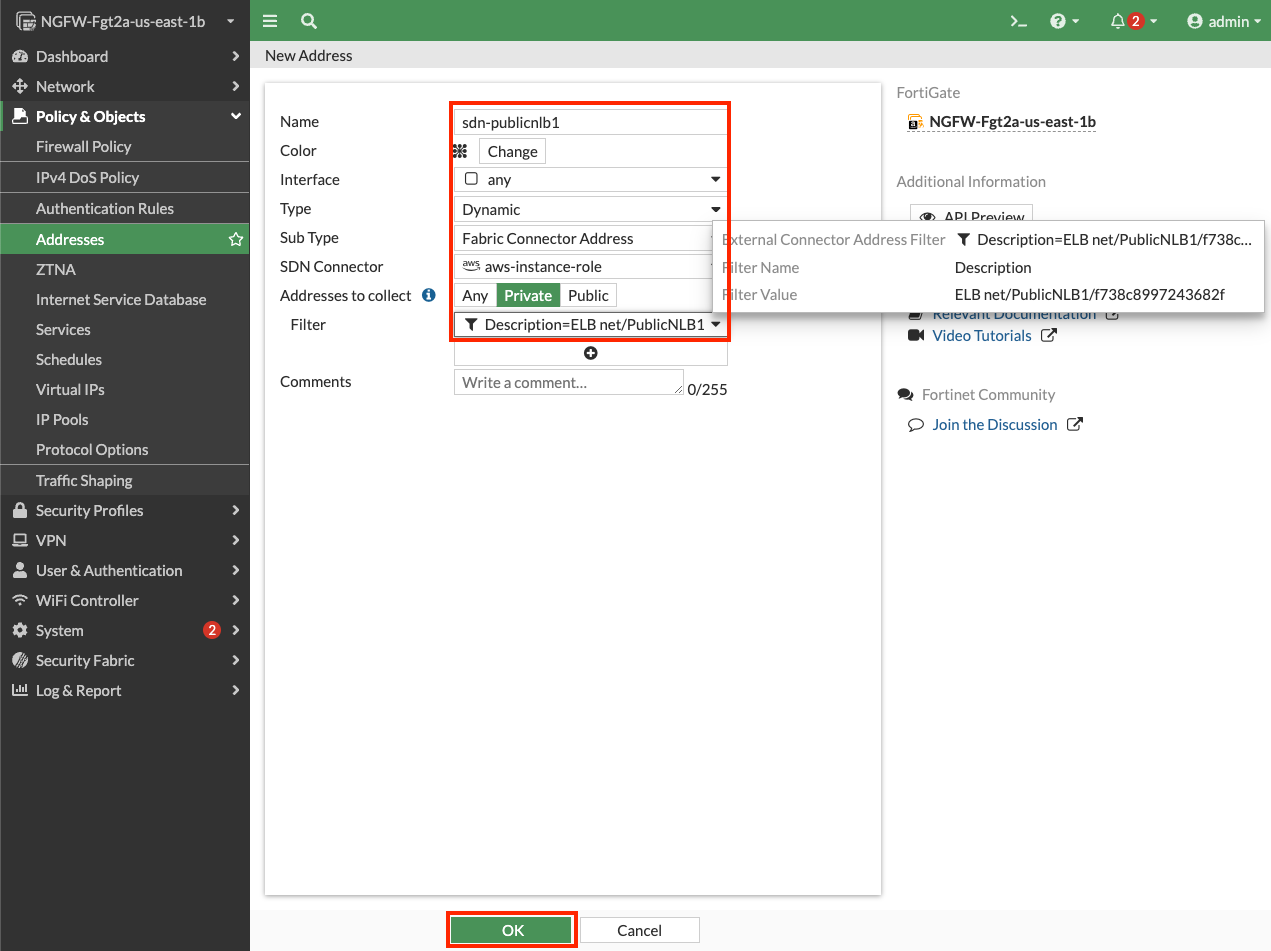
- 2.4: In the FortiGate GUI, navigate to Policy & Objects > Addresses, and click Create new.
- 2.5: Create a dynamic address object with the settings shown below, including searching for the NLB with PublicNLB1 to find the full filter, then click OK.
Tip
Dynamic address objects allow creating address objects based on resource metadata such as VPC ID, Auto Scale Group, EKS Cluster or Pod, and even Tag Name + Value pairs applied to the resource. FortiOS is using AWS API calls behind the scenes such as ec2:DescribeInstances, ec2:DescribeNetworkInterfaces, eks:ListClusters, eks:DescribeCluster, etc. to find running resources to match based on metadata (AWS, Kubernetes, etc) and pull their IP address information. This is done on a frequent basis to keep the dynamic address object up to date automatically. To learn more about all the public and private clouds this feature supports, check out our documentation.
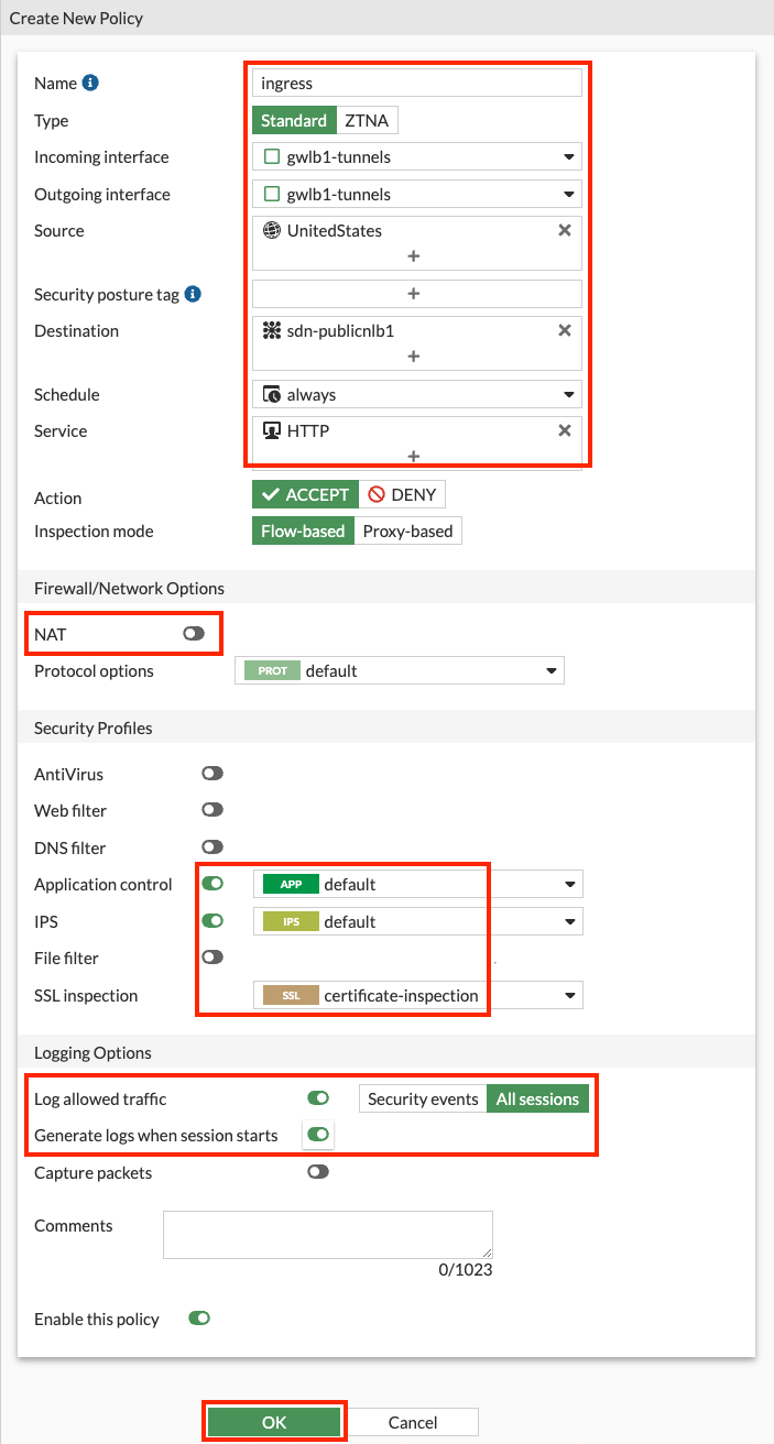
- 2.6: Navigate to Policy & Objects > Firewall Policy and click Create new.
- 2.7: Create a new policy with the settings shown below and click OK to allow ingress traffic to the Public NLB in VPC-A.
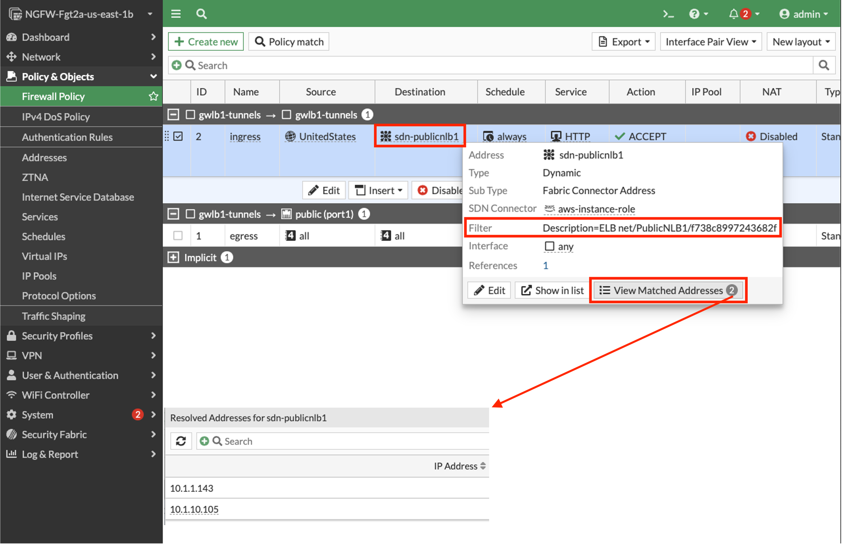
- 2.8: Validate that the dynamic address objects are automatically populated by hovering over both objects. In the popup menu, click View Matched Addresses button.
- 2.9: Repeat the above steps on FortiGate2 as this is an Active-Active design.
Info
You can use FortiManager to manage a single policy set (FW policies, address & security objects, etc) and apply this across multiple FortiGates in the same or different deployments. Alternatively, if you are using FortiGate Auto Scale, then there is configuration sync that occurs from the config-primary to all config-secondaries in the Auto Scale Group.
3) Test distributed ingress to Public NLB1 (and Instance-A) through GWLB and the FortiGates
Detailed Steps…
3.1: Navigate to the CloudFormation Console and toggle View Nested to off.
3.2: Select the main template and select the Outputs tab.
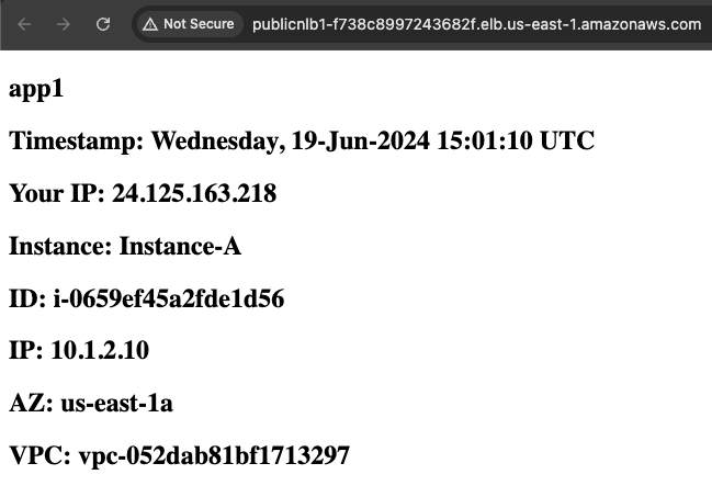
3.3: Copy the URL from Application1URL and navigate to this in your browser.
3.4: You should see the web page with Instance-A and your connection details.
4) Let’s dig deeper to understand how all of this works
Detailed Steps…
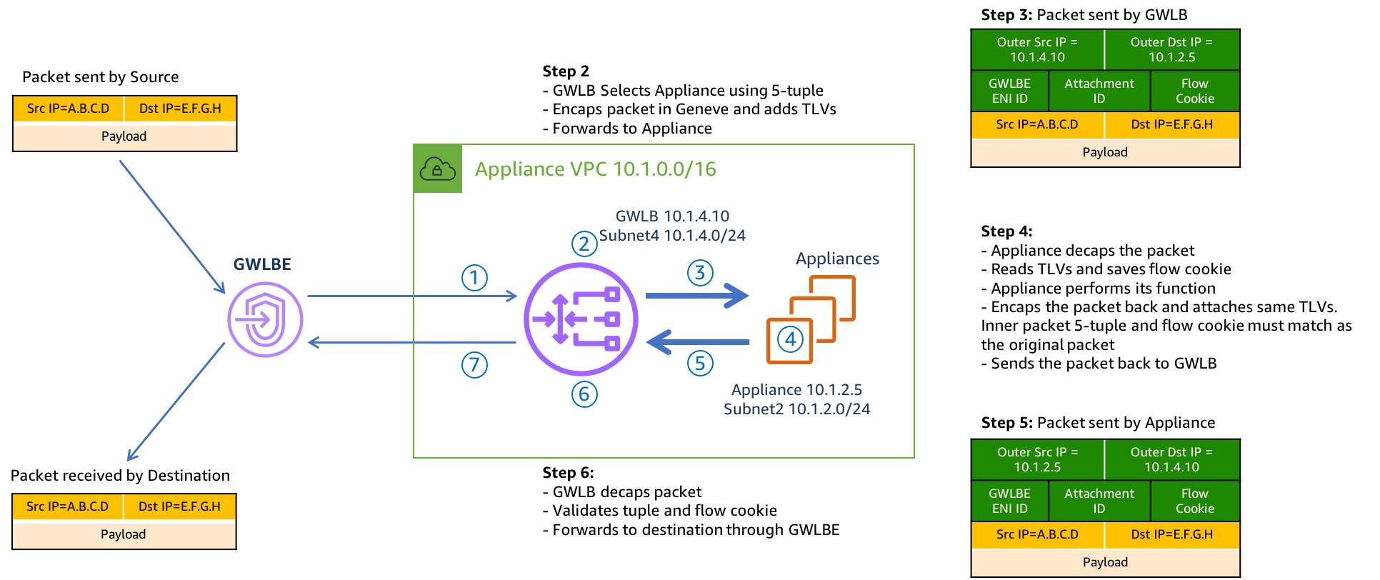
4.1 Here is an example of how GWLB routing works at a low level, including what information is tracked, and included in the GENEVE tunnel headers.
4.2 To see this in your own environment, you can use the steps below. You will need Wireshark installed or another tool to handle .pcap files to do this.
4.3 In the FortiGate GUI (either one), navigate to Network > Diagnostics > Packet Capture.
4.4 Create a new packet capture with the settings shown below and click Start capture to see GENEVE traffic. Keep in mind that this is an active-active setup, so sessions are being sent to both FortiGates. You may need to generate multiple sessions before traffic is captured on your current FortiGate.
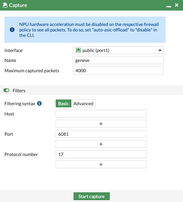
4.5 After enough packets have been seen, click Stop capture, then click Save as .pcap.
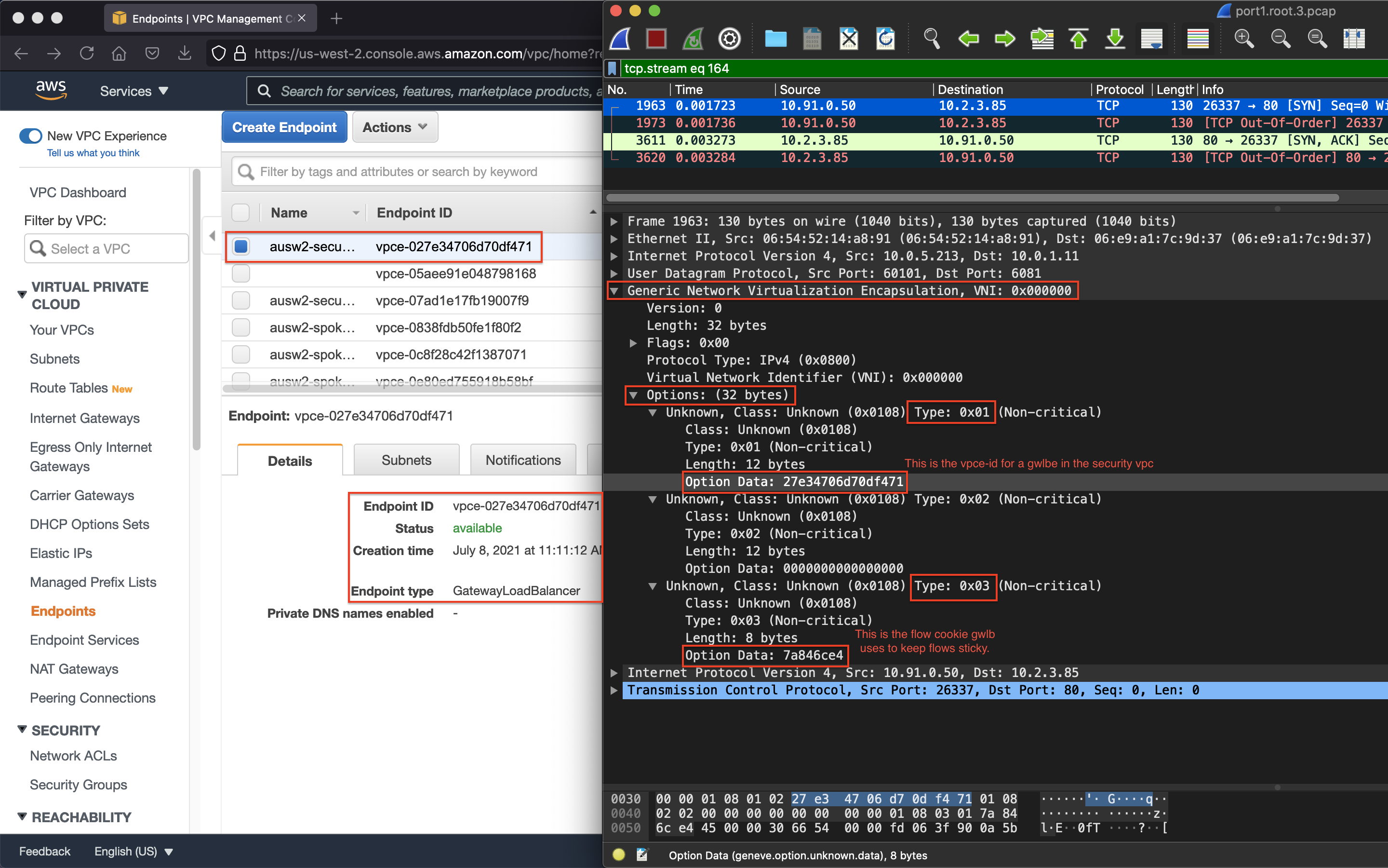
4.6 Open the .pcap file and drill into the GENEVE header like shown at the beginning of this section to find the GWLBVPC Endpoint and match this to the endpoints seen in your VPC console. Keep in mind that leading zeros of the endpoint ID are not listed in Wireshark.
Info
Gateway Load Balancer provides a very scalable Active-Active design for bump in the wire inspection with FortiGates applying NGFW, SSL MitM, etc. This is a regional setup that can support VPCs regardless if there is centralized networking (ie Transit Gateway used) or more of a distributed setup (each VPC is an island).
Gateway Load Balancer receives all traffic through Gateway Load Balancer Endpoints (ie GWLBE also called VPC Endpoints or VPCE for short). GWLB does not have a route table to track source CIDRs but rather relies on the GWLBE/VPCE ID and will return inspected traffic directly back to the endpoint for VPC routing to then take over.
Gateway Load Balancer is both a gateway in that it can be (more specifically the GWLBE/VPCE) a route target, and it is a load balancer in that it is flow aware (tracks 3/5 tuple flows) and keeps flows sticky to each FortiGate.
The GWLBE/VPCE ID, a flow cookie, and other information are stored and passed to the FortiGates via the GENEVE tunnel headers. Geneve is similar to VXLAN with optional TLVs (type length value options in the headers) to provide more context on the encapsulated data-plane traffic. Reference AWS Documentation to find out more.
On a side note, since GWLB does not track source CIDRs for routing, this means that both GWLB and the FortiGates can support environments where there are overlapping CIDR blocks. You can inspect this traffic in the same regional deployment, but this means you would be applying the same FW policies to the traffic. It is best practice to either use separate deployments or to use VDOMs and map your traffic from each GWLBE/VPCE to different VDOMs so that you can apply unique FW policies.
- 4.7 Below is a step by step of the packet handling for the ingress web traffic to Public NLB1 in VPC-A.
| Hop | Component | Description | Packet |
|---|---|---|---|
| 1 | Internet -> 10.1.x.x/24 GWLBE(VPCE) | An inbound connection starts with DNS resolution of the Public NLB to a public IP for one of the Availability Zones. The first packet (TCP sync) will be seen at the IGW attached to the VPC where the NLB is deployed. The IGW will perform destination NAT to the private IP of the public NLB and forward this to the GWLBE/VPCE as configured in VPC-A-IgwRouteTable. | x.x.x.x:src-port -> 10.1.x.x:80 |
| 2 | GWLBE(VPCE) -> GWLB | GWLBE/VPCE will route the traffic to the associated GWLB network interface in the same Availability Zone. This is done behind the scenes using AWS Private Link. | x.x.x.x:src-port -> 10.1.x.x:80 |
| 3 | GWLB -> FGTs-Port1 | GWLB receives the traffic, encapsulates this in a GENEVE tunnel and forwards this flow to one of the FGTs. Post inspection the FGTs return the traffic to GWLB, which then hairpins the traffic back to the original GWLBE/VPCE | x.x.x.x:src-port -> 10.1.x.x:80 |
| 4 | GLBE(VPCE) -> 10.1.0.0/16 Local | The GWLBe endpoint will then route the inspected traffic to the intrinsic router. The intrinsic router will route traffic directly to the NLB’s ENI as specified in the VPC route table assigned to the subnet. | x.x.x.x:src-port -> 10.1.x.x:80 |
| 5 | NLB -> Instance-A | The NLB will send traffic to a healthy target, in either AZ since cross zone load balancing is enabled. Instance-A is the only target so it receives the traffic | x.x.x.x:src-port -> 10.1.2.10:80 |
| 6 | Instance-A -> NLB | Instance-A will receive the traffic and respond. The return traffic will follow these steps in reverse. | 10.1.2.10:80 -> x.x.x.x:src-port |
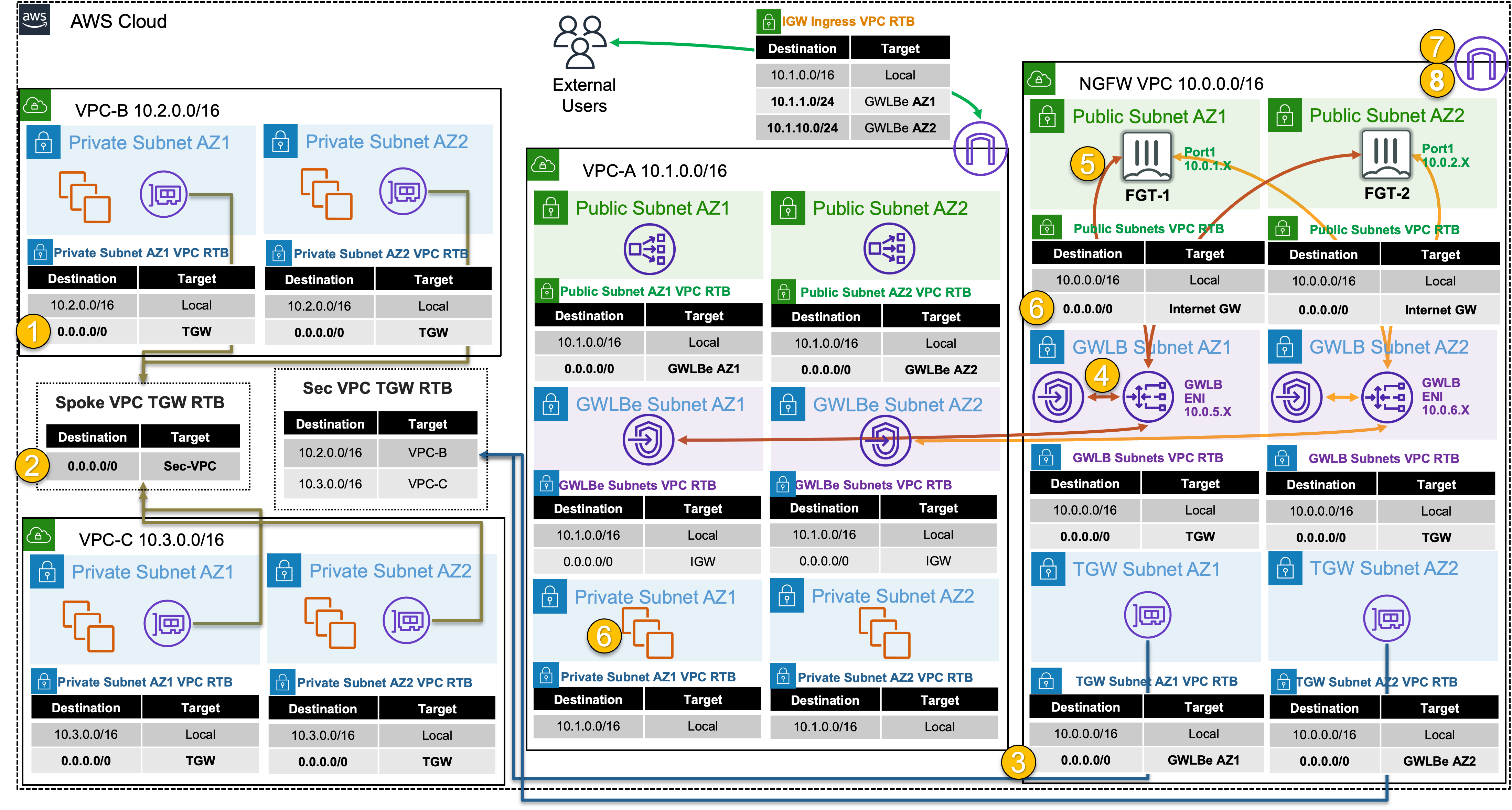
5) Test centralized egress from Instance-B through GWLB & the FortiGates
6) Let’s dig deeper to understand how all of this works
Detailed Steps…
- 6.1: Note that the output of
curl ipinfo.ioreturned the public IP of one of the FortiGates connected to GWLB. If you continue to run the command multiple times, you will see that your outbound traffic is flowing through both FortiGates and being Source NAT’d to look like traffic is coming from their Elastic IPs.
Info
One-Arm Model
GWLB supports two different models of firewall deployments, one-arm and two-arm where a firewall appliance can also perform NAT.
In the one-arm model, the FortiGates will inspect traffic and forward this back to GWLB where Internet bound traffic has NAT applied by a NAT GW. Typically, the NAT GW will be in a workload VPC in a distributed design. Distributed designs have GWLB endpoints in each workload VPC requiring an attached Internet Gateway (IGW) and public load balancer or NAT GW. A centralized design can use NAT GW in an inspection VPC for centralized egress and have GWLB endpoints only deployed in the inspection VPC (no need for GWLB endpoints in each workload VPC).
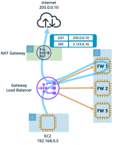
We can use static and policy routes like below to support this setup. In a 2 AZ deployment there are two static routes using priority setting to bypass the reverse path filtering check when receiving data plane traffic over the GENEVE tunnels. The static routes are default routes to simplify the config, but you could also specify a route for each spoke VPC for each GENEVE tunnel. Also, there are two policy routes to hairpin traffic received over each GENEVE tunnel, back to the same tunnel.
config router static
edit 1
set distance 5
set priority 100
set device gwlb1-az1
next
edit 2
set distance 5
set priority 100
set device gwlb1-az2
next
end
config router policy
edit 1
set input-device gwlb1-az1
set output-device gwlb1-az1
next
edit 2
set input-device gwlb1-az2
set output-device gwlb1-az2
next
Two-Arm Model
In the two-arm model, the FortiGates will inspect traffic, forward, & SNAT traffic out port1 (public interface) to act as a NAT GW. This removes the need for deploying NAT GWs in each AZ of each workload VPC. This is typically used in a centralized design where the data plane traffic used TGW to reach the GWLB endpoints in the inspection/security VPC and be inspected by the FortiGates. In summary centralized vs distributed designs is in reference to the GWLB endpoint placement which impacts how traffic is routed to these for inspection of traffic for different directions (ingress, egress, and east/west).
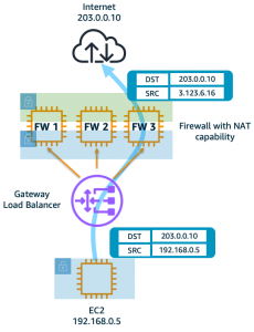
We can use static and policy routes like below to support this setup. In a 2 AZ deployment there are two static routes using priority setting to bypass the reverse path filtering check when receiving data plane traffic over the GENEVE tunnels. The static routes are default routes to simplify the config, but you could also specify a route for each spoke VPC for each GENEVE tunnel. Also, there are two policy routes to hairpin traffic received over each GENEVE tunnel, back to the same one. These policy routes will only hairpin traffic destined RFC1918 addresses and will route internet bound traffic out port1.
config router static
edit 1
set distance 5
set priority 100
set device gwlb1-az1
next
edit 2
set distance 5
set priority 100
set device gwlb1-az2
next
end
config router policy
edit 1
set input-device gwlb1-az1
set dst "10.0.0.0/255.0.0.0" "172.16.0.0/255.240.0.0" "192.168.0.0/255.255.0.0"
set output-device gwlb1-az1
next
edit 2
set input-device gwlb1-az2
set dst "10.0.0.0/255.0.0.0" "172.16.0.0/255.240.0.0" "192.168.0.0/255.255.0.0"
set output-device gwlb1-az2
next
Supporting Both Models
In a single region, you can have one deployment of FGTs & GWLB support both distributed and centralized designs. This all comes down to implementing the appropriate routing at the VPC & TGW route tables and FortiGates. For examples on the VPC & TGW routes for different designs, reference common architecture patterns.
Here is an example of the static & policy routes to support a distributed spoke1 VPC (CIDR 10.1.0.0/16) and centralized spoke2 VPC.
config router static
edit 1
set distance 5
set priority 100
set device gwlb1-az1
next
edit 2
set distance 5
set priority 100
set device gwlb1-az2
next
end
config router policy
edit 1
set input-device gwlb1-az1
set src "10.1.0.0/16"
set output-device gwlb1-az1
next
edit 2
set input-device gwlb1-az2
set src "10.1.0.0/16"
set output-device gwlb1-az2
next
edit 3
set input-device gwlb1-az1
set dst "10.0.0.0/255.0.0.0" "172.16.0.0/255.240.0.0" "192.168.0.0/255.255.0.0"
set output-device gwlb1-az1
next
edit 4
set input-device gwlb1-az2
set dst "10.0.0.0/255.0.0.0" "172.16.0.0/255.240.0.0" "192.168.0.0/255.255.0.0"
set output-device gwlb1-az2
next- 6.2 Below is a step by step of the packet handling for the centralized egress from Instance-B.
| Hop | Component | Description | Packet |
|---|---|---|---|
| 1 | Instance-B -> 0.0.0.0/0 TGW | Instance-B sends egress traffic to the VPC router (its default gw) which routes traffic to TGW as configured in the VPC-B-Private1RouteTable. | 10.2.2.10:src-port -> y.y.y.y:80 |
| 2 | VPC-B-TGW-Attachment -> 0.0.0.0/0 NGFW-security-vpc-attachment | VPC-B-TGW-Attachment is associated to the Spoke VPC TGW RTB. This TGW RTB has a default route to NGFW-security-vpc-attachment, so traffic is forwarded there. | 10.2.2.10:src-port -> y.y.y.y:80 |
| 3 | NGFW-security-vpc-attachment -> 0.0.0.0/0 VPCE-… | NGFW-security-vpc-attachment is attached to the NGFW VPC TGW Attach Subnets which have a default route to the GWLBE/VPCE in the same Availability Zone. | 10.2.2.10:src-port -> y.y.y.y:80 |
| 4 | GWLBE/VPCE -> GWLB | GWLBE/VPCE will route traffic to the associated GWLB network interface in the same Availability Zone. This is done behind the scenes using AWS Private Link | 10.2.2.10:src-port -> y.y.y.y:80 |
| 5 | GWLB -> FGTs-Port1 | GWLB receives the traffic, encapsulates this in a GENEVE tunnel and forwards this flow to one of the FGTs. | 10.2.2.10:src-port -> y.y.y.y:80 |
| 6 | FGTs-Port1 -> 0.0.0.0/0 IGW | FGTs changes the source IP to the private IP of Port1 as this has an EIP associated. FGTs sends inspected & allowed traffic to the VPC router via Port1 (its default gw), which routes traffic to the IGW as configured in the NGFW Public Subnet VPC Route Table. | 10.0.x.x:src-port -> y.y.y.y:80 |
| 7 | IGW -> Internet | IGW changes the source IP to the associated EIP of FortiGates Port1 and routes traffic to the internet. | z.z.z.z:src-port -> y.y.y.y:80 |
| 8 | Internet -> IGW | IGW receives reply traffic and changes the source IP to the private IP of FortiGates Port1. The VPC router routes traffic to FortiGates Port1. The return traffic will follow these steps in reverse. | y.y.y.y:80 -> 10.0.x.x:src-port |
7. Lab environment teardown
Discussion Points
- GWLB is a regional service that is both a gateway (VPC route target) and a flow aware load balancer
- This allows very scalable active-active inspection for all directions of traffic
- No SNAT requirement to achieve flow symmetry to the correct FortiGate as GWLB is flow aware
- GWLB and FortiGates supports one and two arm mode (distributed vs centralized egress access & NAT GW replacement)
- GWLB has adjustable TCP idle timers but static UDP idle timers
- GWLB supports cross-zone load balancing and rebalancing of flows on target failover
- Jumbo frames (8500 bytes) are supported
- Inspection VPC handles FortiGate NGFW inspection for any traffic flow (Inbound, Outbound, East/West) and for any network design (distributed vs centralized)
- Appliance Mode is required for this design to keep flows sticky to the correct availability zone which in turn means the correct GWLB endpoint.
- Advanced architectures for all of these scenarios can be found here
This concludes this task