Firewall Architecture
Overview
FortiGate instances can operate in single-arm (1-ARM) or dual-arm (2-ARM) network configurations, fundamentally changing traffic flow patterns through the firewall.
Configuration
firewall_policy_mode = "1-arm" # or "2-arm"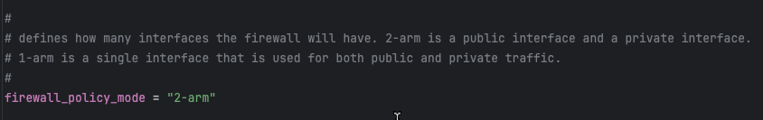
2-ARM Configuration (Recommended for Most Deployments)
Architecture Overview
The 2-ARM configuration deploys FortiGate instances with distinct “trusted” (private) and “untrusted” (public) interfaces, providing clear network segmentation.
Traffic Flow:
- Traffic arrives at GWLB Endpoints (GWLBe) in the inspection VPC
- GWLB load-balances traffic across healthy FortiGate instances
- Traffic encapsulated in Geneve tunnels arrives at FortiGate port1 (data plane)
- FortiGate inspects traffic and applies security policies
- Internet-bound traffic exits via port2 (public interface)
- Port2 traffic is source-NATed via EIP or NAT Gateway
- Return traffic follows reverse path back through Geneve tunnels
Interface Assignments
- port1: Data plane interface for GWLB connectivity (Geneve tunnel termination)
- port2: Public interface for internet egress (with optional dedicated management when enabled)
Network Interfaces Visualization
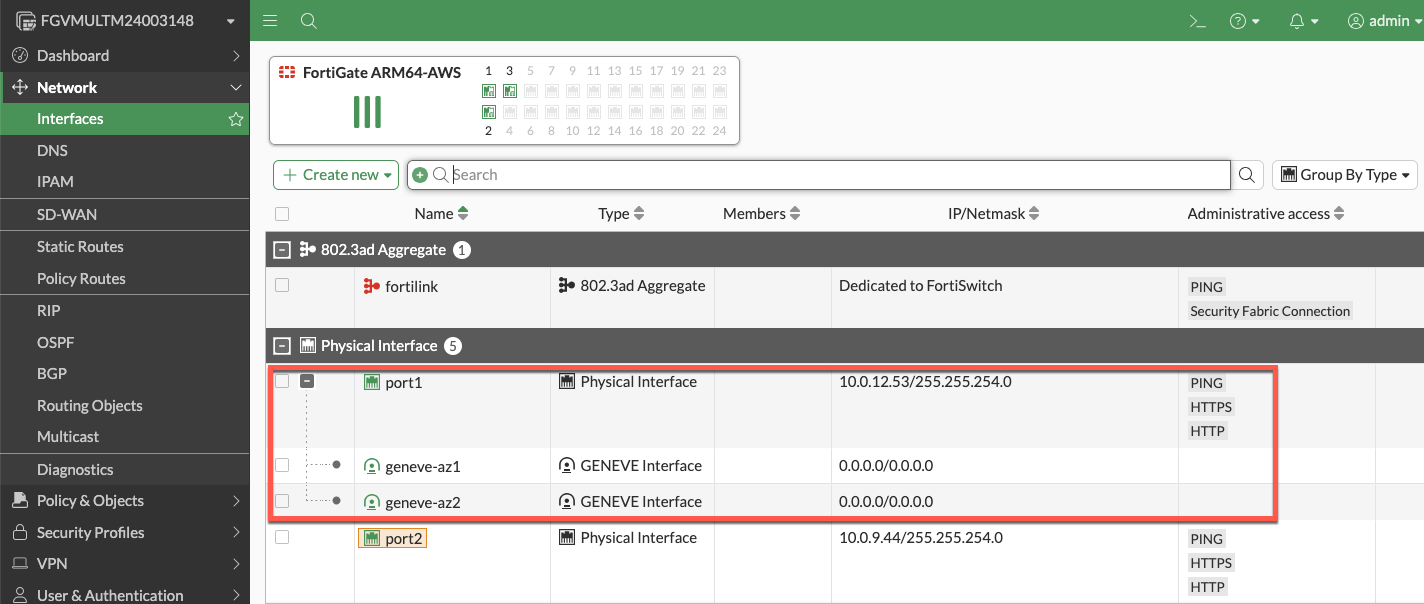
The FortiGate GUI displays both physical interfaces and logical Geneve tunnel interfaces. Traffic inspection occurs on the logical tunnel interfaces, while physical port2 handles egress.
Advantages
- Clear network segmentation: Separate trusted and untrusted zones
- Traditional firewall model: Familiar architecture for network security teams
- Simplified policy creation: North-South policies align with interface direction
- Better traffic visibility: Distinct ingress/egress paths ease troubleshooting
- Dedicated management option: Port2 can be isolated for management traffic
Best Use Cases
- Production deployments requiring clear network segmentation
- Environments with security policies mandating separate trusted/untrusted zones
- Architectures where dedicated management interface is required
- Standard north-south inspection use cases
1-ARM Configuration
Architecture Overview
The 1-ARM configuration uses a single interface (port1) for all data plane traffic, eliminating the need for a second network interface.
Traffic Flow:
- Traffic arrives at port1 encapsulated in Geneve tunnels from GWLB
- FortiGate inspects traffic and applies security policies
- Traffic is hairpinned back through the same Geneve tunnel it arrived on
- Traffic returns to originating distributed VPC through GWLB
- Distributed VPC uses its own internet egress path (IGW/NAT Gateway)
This “bump-in-the-wire” architecture is the typical 1-ARM pattern for distributed inspection, where the FortiGate provides security inspection but traffic egresses from the spoke VPC, not the inspection VPC.
Important Behavior: Stateful Load Balancing
GWLB Statefulness: The Gateway Load Balancer maintains connection state tables for traffic flows.
Primary Traffic Pattern (Distributed Architecture):
- ✅ Traffic enters via Geneve tunnel → FortiGate inspection → Hairpins back through same Geneve tunnel
- ✅ Distributed VPC handles actual internet egress via its own IGW/NAT Gateway
- ✅ This “bump-in-the-wire” model provides security inspection without routing traffic through inspection VPC
Key Requirement: Symmetric routing through the GWLB. Traffic must return via the same Geneve tunnel it arrived on to maintain proper state table entries.
Info
Centralized Egress Architecture (Transit Gateway Pattern)
In centralized egress deployments with Transit Gateway, the traffic flow is fundamentally different and represents the primary use case for internet egress through the inspection VPC:
Traffic Flow:
- Spoke VPC traffic routes to Transit Gateway
- TGW routes traffic to inspection VPC
- Traffic enters GWLBe (same AZ to avoid cross-AZ charges)
- GWLB forwards traffic through Geneve tunnel to FortiGate
- FortiGate inspects traffic and applies security policies
- Traffic exits port1 (1-ARM) or port2 (2-ARM) toward internet
- Egress via EIP or NAT Gateway in inspection VPC
- Response traffic returns via same interface to same Geneve tunnel
This is the standard architecture for centralized internet egress where:
- All spoke VPCs route internet-bound traffic through the inspection VPC
- FortiGate autoscale group provides centralized security inspection AND NAT
- Single egress point simplifies security policy management and reduces costs
- Requires careful route table configuration to maintain symmetric routing
When to use: Centralized egress architectures where spoke VPCs do NOT have their own internet gateways.
Note
Distributed Architecture - Alternative Pattern (Advanced Use Case)
In distributed architectures where spoke VPCs have their own internet egress, it is possible (but not typical) to configure traffic to exit through the inspection VPC instead of hairpinning:
- Traffic enters via Geneve tunnel → Exits port1 to internet → Response returns via port1 to same Geneve tunnel
This pattern requires:
- Careful route table configuration in the inspection VPC
- Specific firewall policies on the FortiGate
- Proper symmetric routing to maintain GWLB state tables
This is rarely used in distributed architectures since spoke VPCs typically handle their own egress. The standard bump-in-the-wire pattern (hairpin through same Geneve tunnel) is recommended when spoke VPCs have internet gateways.
Interface Assignments
- port1: Combined data plane (Geneve) and egress (internet) interface
Advantages
- Reduced complexity: Single interface simplifies routing and subnet allocation
- Lower costs: Fewer ENIs to manage and potential for smaller instance types
- Simplified subnet design: Only requires one data subnet per AZ
Considerations
- Hairpinning pattern: Traffic typically hairpins back through same Geneve tunnel
- Higher port1 bandwidth requirements: All traffic flows through single interface (both directions)
- Limited management options: Cannot enable dedicated management ENI in true 1-ARM mode
- Symmetric routing requirement: All traffic must egress and return via port1 for proper state table maintenance
Best Use Cases
- Cost-optimized deployments with lower throughput requirements
- Simple north-south inspection without management VPC integration
- Development and testing environments
- Architectures where simplified subnet design is prioritized
Comparison Matrix
| Factor | 1-ARM | 2-ARM |
|---|---|---|
| Interfaces Required | 1 (port1) | 2 (port1 + port2) |
| Network Complexity | Lower | Higher |
| Cost | Lower | Slightly higher |
| Management Isolation | Not available | Available |
| Traffic Pattern | Hairpin (distributed) or egress (centralized) | Clear ingress/egress separation |
| Best For | Simple deployments, cost optimization | Production, clear segmentation |
Next Steps
After selecting your firewall architecture, proceed to Dedicated Management ENI to learn about management plane isolation options.