FortiOS FGCP A/P HA in AWS


The purpose of this site is to provide documentation on how FortiOS FGCP HA works in AWS post deployment, during a failover event, and best practice for common use cases.
For other documentation needs such as FortiOS administration, please reference docs.fortinet.com.
FortiOS supports using FGCP (FortiGate Clustering Protocol) in unicast form to provide an active-passive clustering solution for deployments in AWS. This feature shares a majority of the functionality that FGCP on FortiGate hardware provides with key changes to support AWS SDN (Software Defined Networking).
This solution works with two FortiGate instances configured as a master and slave pair and that the instances are deployed in different subnets and different availability zones within a single VPC. These FortiGate instances act as a single logical instance and do not share interface IP addressing as they are in different subnets. You can deploy these in the same subnets and availability zone if desired and share secondary interface IP addressing, however this is a less common design.
The main benefits of this solution are:
For further information on FGCP reference the High Availability chapter in the FortiOS Handbook on the Fortinet Documentation site.
Note: Other Fortinet solutions for AWS such as FGCP HA (Single AZ), AutoScaling, and Transit Gateway are available. Please visit www.fortinet.com/aws for further information.
FGCP HA provides AWS networks with enhanced reliability through device fail-over protection, link fail-over protection, and remote link fail-over protection. In addition, reliability is further enhanced with session fail-over protection for most IPv4 and IPv6 sessions including TCP, UDP, ICMP, IPsec\SSL VPN, and NAT sessions.
A FortiGate FGCP cluster appears as a single logical FortiGate instance and configuration synchronization allows you to configure a cluster in the same way as a standalone FortiGate unit. If a fail-over occurs, the cluster recovers quickly and automatically and can also send notifications to administrator so that the problem that caused the failure can be corrected and any failed resources restored.
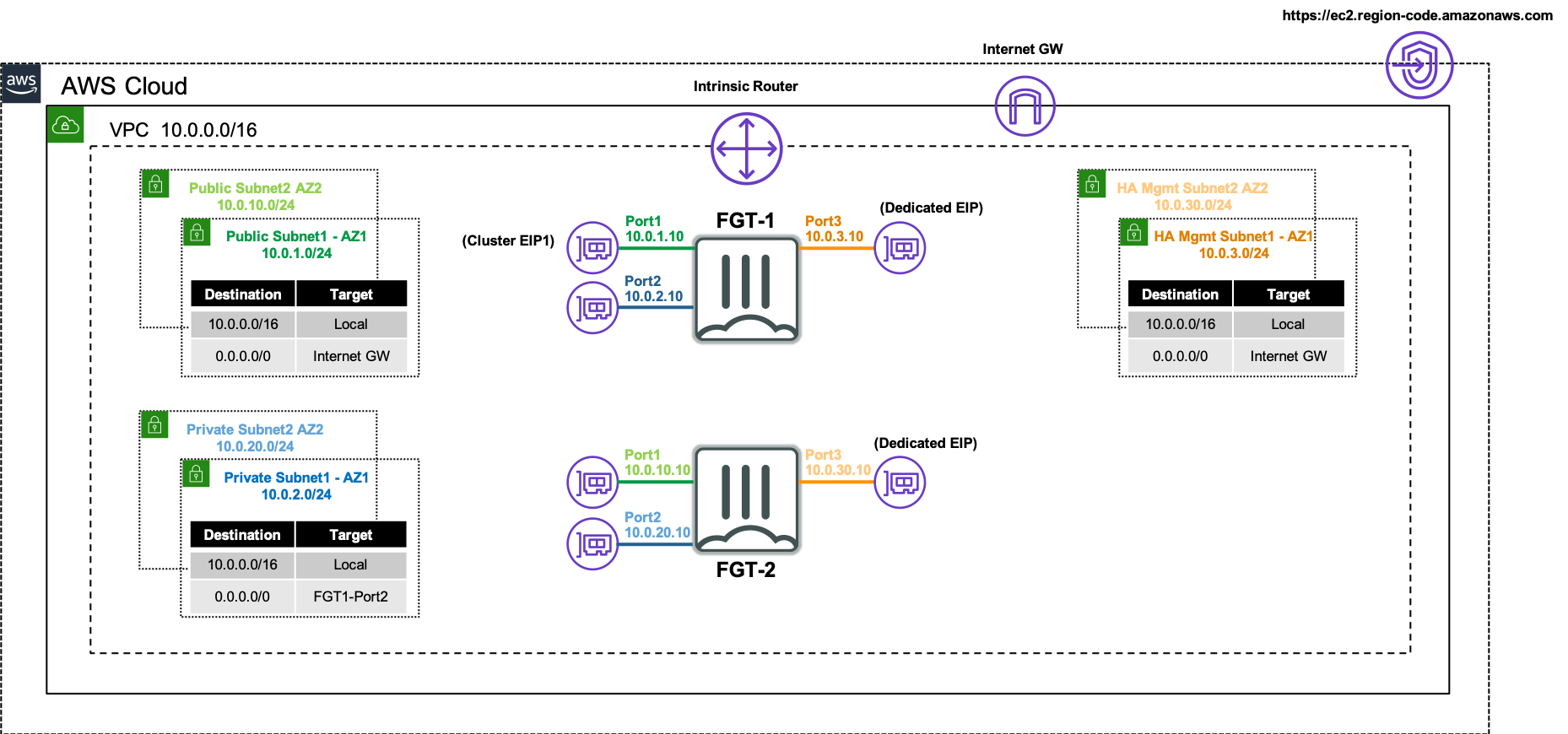
The FortiGate instances will use multiple interfaces for data plane and control plane traffic to achieve FGCP clustering in an AWS VPC. The FortiGate instances require four ENIs for this solution to work as designed so make sure to use an AWS EC2 instance type that supports this. Reference AWS Documentation for further information on this.
For data plane functions the FortiGates will use two dedicated ENIs, one for a public interface (ie ENI0\port1) and another for a private interface (ie ENI1\port2). These ENIs will utilize primary IP addressing and FortiOS should not sync the interface configuration (config system interface) or static routes (config router static) as these FGTs are in separate subnets. This is controlled via the CLI (config system vdom-exception). Thus when configuring these items, you should do so individually on both FortiGates.
A cluster EIP will be associated to the primary IP of the public interface (ie ENI0\port1) of the current master FortiGate instance and will be reassociated to a new master FortiGate instance as well.
For control plane functions, the FortiGates will use a dedicated ENI (ie ENI2\port3) for HA management access to each instance and also allow each instance to independently and directly communicate with the public AWS EC2 API. This dedicated interface is critical to failing over AWS SDN properly when a new FGCP HA master is elected and is the only method of access available to the current slave FortiGate instance.
Depending on the FortiOS version, the FortiGates will either reuse the HA management interface (ie ENI2\port3) or use another dedicated ENI (ie ENI3\port4) for FGCP HA communication to perform tasks such as heartbeat checks, configurationport4 sync, and session sync. In FortiOS 7.0.x and newer versions, one ENI will be used for both HA management and communication channels.
The FortiGates are configured to use the unicast version of FGCP by applying the configuration below on both the master and slave FortiGate instances. This configuration is automatically configured and bootstrapped to the instances when deployed by the provided CloudFormation or Terraform Templates.
config system vdom-exception
edit 1
set object sytem.interface
next
edit 2
set object router.static
next
end
config system ha
set group-name "group1"
set mode a-p
set hbdev "port3" 50
set session-pickup enable
set ha-mgmt-status enable
config ha-mgmt-interface
edit 1
set interface port3
set gateway 10.0.3.1
next
end
set override disable
set priority 255
set unicast-hb enable
set unicast-hb-peerip 10.0.30.10
end
config system vdom-exception
edit 1
set object sytem.interface
next
edit 2
set object router.static
next
end
config system ha
set group-name "group1"
set mode a-p
set hbdev "port3" 50
set session-pickup enable
set ha-mgmt-status enable
config ha-mgmt-interface
edit 1
set interface port3
set gateway 10.0.30.1
next
end
set override disable
set priority 1
set unicast-hb enable
set unicast-hb-peerip 10.0.3.10
end
Note the config system vdom-exception section. Since the FortiGates are deployed in different Availability Zones, they are in separate subnets and can’t share or sync their physical interface IPs or static routes due to next hop IP address being different. Reference vdom-exceptions to find out more. In general, you will only need this for physical interfaces and static routes. Enabling this for other items such as VIPs can add complexity when working with FortiManager.
The FortiGate instances will make calls to the public AWS EC2 API to update AWS SDN to failover both inbound and outbound traffic flows to the new master FortiGate instance. There are a few components that make this possible.
FortiOS will assume IAM permissions to access the AWS EC2 API by using the IAM instance role attached to the FortiGate instances. The instance role is what grants the required permissions for FortiOS to:
The FortiGate instances will utilize their independent and direct internet access available through the FGCP HA management interface (ie ENI2\port3) to access the public AWS EC2 API. It is critical that this ENI is in a public subnet with an EIP assigned so that each instance has independent and direct access to the internet or the AWS SDN will not reference the current master FortiGate instance which will break data plane traffic.
There is an option to deploy the FortiGates to where the FGCP HA management interface (ie ENI2\port3) can access AWS EC2 API via private VPC endpoints and would not require dedicated EIPs. However, this comes with caveats to consider.
First, a dedicated method of access to the FortiGate instances needs to be setup to allow dedicated access to the HAmgmt interfaces. This method of access should not use the master FortiGate instance so that either instance can be accessed regardless of the cluster status. Examples of dedicated access are Direct Connect, IPsec VPN connections to an attached AWS VPN Gateway, or using Transit Gateway. Reference AWS Documentation for further information.
Second, the FortiGates should be configured to use the ‘169.254.169.253’ IP address for the AWS intrinsic DNS server as the primary DNS server to allow proper resolution of AWS API hostnames during failover to a new master FortiGate. Here is an example of how to configure this with CLI commands:
config system dns
set primary 169.254.169.253
end
Finally, the VPC interface endpoint needs to be deployed into both of the HAmgmt subnets and must also have ‘Private DNS’ enabled to allow DNS resolution of the default AWS EC2 API public hostname to the private IP address of the VPC endpoint. This means that the VPC also needs to have both DNS resolution and hostname options enabled as well. Reference AWS Documentation for further information.
For further details on FGCP and its components, reference the High Availability chapter in the FortiOS Handbook on the Fortinet Documentation site.
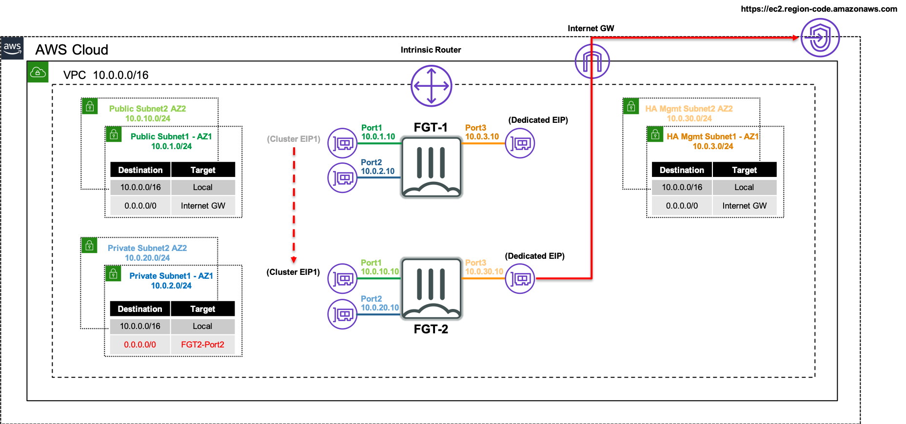
The following network diagram will be used to illustrate a failover event from the current master FortiGate (FortiGate 1), to the current slave FortiGate (FortiGate 2).
Inbound failover is provided by reassigning the EIPs associated to the primary IP address of ENI0\port1 from FortiGate 1’s public interface to FortiGate 2’s public interface.
Outbound failover is provided updating any route targets referencing FortiGate 1’s private interface reference FortiGate 2’s private interface.
The AWS SDN updates are performed by FortiGate 2 initiating API calls from the dedicated HA management interface (ie ENI2\port3) through the AWS Internet Gateway.
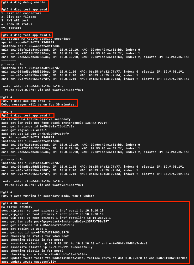
To validate that the FortiGates can assume at least read only permissions about themselves, you can use the commands below on either the master or slave. This will send requests to the instance metadata service and EC2 api.
diag debug enable
diag test app awsd 4
To enable more verbose debugging output with the test command above or for an actual HA failover event, use the commands below.
diag debug enable
diag debug app awsd -1
To disable and reset the debugging levels, use the commands below.
diag debug reset
diag debug disable

Here is an example of running test and debug commands before a failover event to get more verbose output. Notice the EIP and VPC route replacements to reference the new master FortiGate 2.
It is best practice to use Infrastructure as Code (IaC) templates to deploy FGCP in AWS as there are quite a bit of components that make up the entire solution. These can be used to deploy with a new VPC or to use an existing VPC. You can also integrate with a new or existing Transit Gateway as well.
Reference the CloudFormation and Terraform templates in the Github repos below and reference the quick start guides for how to use these for a deployment.
You will need administrator privileges to run these templates as they are creating IAM roles, policies, and other resources that are required for the solution and automating deployment.
fortigate-aws-ha-dualaz-cloudformation
fortigate-aws-ha-dualaz-terraform
This is picking up after a successful deployment of FGCP with CloudFormation. The same steps can be used, post deployment, to validate a successful setup and test failover.


*** Note: Due to browser caching issues, the icon for Synchronization status may not update properly after the cluster is in-sync. So either close your browser and log back into the cluster or alternatively verify the HA config sync status with the CLI command ‘get system ha status’. ***


While waiting for FGCP to synchronize, you can check that the licensing (BYOL in this example) is applied successfully and the base config is applied correctly. You can run the command below on each FortiGate to validate this:
diag debug cloudinit show


Since we use the ‘NewSecurityVPC_FGCP_DualAZ.template.json’ CloudFormation template, a default route was created for us in the appropriate VPC route table. If using the existing VPC templates for either CloudFormation or Terraform, you will need to create the appropriate routes yourself.


If you enabled debugging output on FortiGate 2 before the failover event, you would see debug output which shows what is happening under the covers.

Below, we have listed two common scenarios with VIPs and also have a caveats section for consideration.


Since we are disabling source NAT, there are a few points to consider in your environment:
Service Objects: Since the VIP is configured with port forwarding, it matches based on the configured ‘mapped to’ protocol and destination port. The service object in the FW policy should be configured to with the exact same ‘mapped to’ values or else traffic will not match the VIP and FW Policy as expected.
Security Groups: Make sure your security group applied to the FGT port1 allows the port used in the external service port of the VIP. Also your security group applied to your EC2 instance will need to allow the mapped to port and also a source IP range of ‘0.0.0.0/0’ or whatever CIDR blocks cover your needs. Since the FGT is applying inspection we are fine to leave this as ‘0.0.0.0/0’ for now.
VPC routes: If your EC2 instance is deployed in the same VPC as the FortiGates, the subnet needs to have a VPC route table assigned with a VPC route of ‘0.0.0.0/0’ back to the master FGT port2 ENI. If your EC2 instance is in a different VPC connected via Transit Gateway, then you need VPC routes pointing traffic back to Transit Gateway, and Transit Gateway route tables configured to get traffic back to the security VPC where the FortiGates are.
Troubleshoot: If traffic is not flowing as expected, it is recommended to run a packet capture to validate inbound traffic is making it past the security groups, the traffic is accepted and routed out port2, and return traffic is received. If the traffic does not show in the packet capture, then it is likely a security group or something else external that is blocking the traffic. A quick example of a sniffer we could use for this VIP is diag sniffer packet any “(port 221) or (host 10.0.4.20 and port 22)” 4 0 l. For more examples on how to use the sniffer and other tools, reference documentation.


Even though this is an internal or private load balancer, the DNS A record is a public record which will resolve to the current private IPs of your ALB.
haberra@haberra-mac kpair % nslookup internal-poc-internal-hafc1-1204713825.us-west-1.elb.amazonaws.com
Server:		172.30.1.106
Address:	172.30.1.106#53

Non-authoritative answer:
Name:	internal-poc-internal-hafc1-1204713825.us-west-1.elb.amazonaws.com
Address: 10.0.40.106


You can set the external ip to the matching private IP which is associated to the Cluster IP but this comes with points to consider.
You need to disable syncing all VIPs since the FortiGates are deployed in different Availability Zones, they are in separate subnets and can’t share or sync their physical interface IPs or VIP external IPs (when used). This means you need to configure the VIPs on both FGTs, with the same name etc but different external ip, and then configure FW policy so that all other synced items can be shared.
If FortiManager is used, it can manage these FortiGates while not syncing policy objects but requires additional steps. Reference documentation for more information.
When you need to support multiple web applications that each have unique destinations, it is recommended to use an external Application Load Balancer (ALB) with HTTP based routing rules in front of the FortiGates to break out each application to a unique destination port. This allows each application to match a unique FW policy and VIP for applying the desired L4 and L7 controls to each web application. Also a point to note is the client browser will still be accessing these applications on the standard ports for HTTP/HTTPs. Each ALB listener can support up to 300 HTTP based routing rules so this scales and fails over faster than you could do with multiple Cluster IPs.


http://poc-external-hafc1-1184712227.us-west-1.elb.amazonaws.com/app1/index.html
http://poc-external-hafc1-1184712227.us-west-1.elb.amazonaws.com/app2/index.html
diag sniffer packet any '(tcp port 8001) or (net 10.0.0.0/16 and tcp port 80)' 4 0 l
diag sniffer packet any '(tcp port 8002) or (net 10.0.0.0/16 and tcp port 80)' 4 0 lWhile our simple lab example has all resources in the same VPC, you can use the same design to reach web applications in different VPCs that are reachable through Transit Gateway or other AWS networking components.


When FGCP is deployed using the IaC templates, located here, you already have a single Cluster IP associated to port1 on the master FortiGate. On failover, this Cluster IP is reassociated to port1 on the new master FortiGate. This makes IPsec VPN failover simple for remote devices connecting to a FGCP A/P cluster in AWS. Below is an example of this use case.
While the design is quite simple, there are a few points to consider:
Security Groups: Since these are applied to the FortiGate interfaces, make sure that UDP port 500 & 4500 are allowed for both inbound and outbound rules on port1 of the FortiGates. Also make sure security groups that are applied to port2 of the FortiGates and other relevant resources are allowing communication with the remote network CIDRs.
Elastic IPs (EIP): This is a public IP that can be associated to resources such as EC2 instances and even specific private IPs on an elastic network interfaces (ENIs ie port1). This EIP is used as a static NAT when traffic traverses the Internet Gateway (IGW) of the VPC. This means the FortiGate does not have this public IP directly assigned via DHCP to the port1 interface. Instead port1 will have a private IP, but as traffic is initiated outbound, the IGW will SNAT the traffic to match the associated EIP. The same happens in reverse for inbound traffic.
Local Gateway: In your FortiOS phase 1 configuration, don’t enable ‘Local Gateway’. This is only needed when configuring the FortiGate to use a secondary IP which is associated to an additional EIP (ie Cluster IP #2). When using an FGCP cluster deployed in separate Availability Zones (AZ), this requires disabling the syncing of phase 1 config by adding ‘vpn.ipsec.phase1-interface’ to your config system vdom-exception table. This should only be used for this use case as there is added complexity to consider.
VPC routing: A VPC route is needed in the VPC route table assigned to the private subnets that need to reach the remote networks over the IPsec tunnel. This VPC route(s) should cover all of the remote network CIDRs and point to port2 (ENI1) of the master FortiGate.
FortiOS static routes: Remember that static routes will need to be configured on both FortiGates as they are not synced when deployed in separate subnets (AZs) in AWS.
FortiOS dynamic routing: While FortiGates deployed in separate subnets (AZs) do not sync interface config, you can create a loopback interface with the same name and IP on both FortiGates. This can allow for simple dynamic routing with BGP/OSPF while syncing this config automatically between FortiGates.
Phase 2: It is recommended to enable ‘Auto-negotiate’ and ‘Autokey Keep Alive’ in phase 2 advanced settings to keep phase 2 established at all times.


diag sniffer packet any 'host 10.0.4.161 and 10.1.20.85' 4 0 l


It is recommended to review the IPsec VPN: One Custer IP use case first before using this use case.
FGCP supports moving multiple Elastic IPs (EIPs) on data plane interfaces, which allows the cluster to have multiple Cluster IPs. This is useful when needing to support IPsec tunnels being establish with different Cluster IPs. Below is an example of how to configure this.
Here are a few points to consider:
Secondary IPs: This deign requires the use of secondary private IPs on the AWS Elastic Network Interface (ENI, ie port1) and within FortiOS. Then different EIPs can be associated to each of these on the master FortiGate port1 interface.
Same Count: You should configure the same number of secondary private IPs on both FortiGates within FortiOS and within the AWS ENI settings.
Failover Latency: This design should use as few EIPs as necessary as failover times will increase. This is due to more API calls needing to be made and also waiting for AWS SDN (AWS networking) to implement these changes. As there is no SLA on how quickly these changes are implemented in AWS SDN, you will see some EIPs take quite a bit longer to failover. It is best practice to limit this to no more than 5 EIPs.
Local Gateway: FortiOS requires the use of the ‘Local Gateway’ phase 1 setting to know which secondary IP to use for an IPsec tunnel. Each FortiGate will have different secondary IPs as they are in different subnets & AZs. This requires disabling the syncing of phase 1 & 2 config between the FortiGates by adding vpn.ipsec.phase2-interface and vpn.ipsec.phase2-interface to your config system vdom-exception table.


As syncing of phase 1 & 2 is now disabled, you should be careful to name both phase 1 & 2 with the same name so that FW policy configured on the master will sync to FortiGate 2.


AWS introduced VPC Ingress Routing which allows customers to route ingress traffic (ie traffic destined to a public Elastic IP, EIP) to a different target before reaching the resources with the EIP. With this routing, you can have a design where FortiGates can inspect traffic with L4/L7 controls before routing the clean traffic to the backed resources without VIPs or any NAT required. Below is an example of this use case.
An EIP is a public IP that can be associated to resources such as EC2 instances and even specific private IPs on an elastic network interfaces (ENIs ie port1). This EIP is used as a static NAT when traffic traverses the Internet Gateway (IGW) of the VPC.
While you can associate multiple EIPs directly to the FortiGates and route traffic through while applying NAT, AWS does limit the number of IPs addresses per network interface per instance type. Thus, VPC Ingress Routing was provided to get around this limitation and scales well within a single VPC design.


Since we are not applying any NAT, you need to have a VPC route pointing back to the private interface, port2/eni1, of the master FortiGate. This allows symmetric traffic flow so that reply traffic goes back to the master FortiGate.

diag sniff pack any 'port 80 and (host 10.0.2.124 or 10.0.20.137)' 4 0 l


Yes. FGCP will move over any secondary IPs associated to ENI0\port1 and EIPs associated to those secondary IPs to the new master FortiGate instance. You will need to configure secondary IPs on the ENI via the AWS EC2 Console and in FortiOS for port1. The private IPs configured on the ENI and FortiOS must match.
Yes. FGCP will move any routes (regardless of the network CIDR) found in AWS route tables that are referencing any of the current master FortiGate instance’s data plane ENIs (ENI0\port1, ENI1\port2, etc) to the new master on a failover event.
The existing VPC CloudFormation template is expecting the same VPC configuration that is provisioned in the new Base VPC template. The existing customer VPC would need to have 4 subnets in each of the two availability zones to cover the required Public, Private, HAsync, and HAmgmt subnets. Also ensure that an S3 gateway endpoint deployed and assigned to both of the PublicSubnet’s AWS route table. Another critical point is that all of the Public and HAmgmt subnets need to be configured as public subnets. This means that an IGW needs to be attached to the VPC and a route table, with a default route using the IGW, needs to be associated to the Public and HAmgmt subnets.
The master selection process of FGCP will ignore HA uptime differences unless they are larger than 5 minutes. The HA uptime is visible in the GUI under System > HA. This is expected and the default behavior of FortiOS but can be changed in the CLI under the ‘config system ha’ table. For further details on FGCP master selection and how to influence the process, reference primary unit selection section of the High Availability chapter in the FortiOS Handbook on the Fortinet Documentation site.
Confirm the FortiGates configuration are in-sync and are properly selecting a new master by seeing the HA role change as expected in the GUI under System > HA or CLI with ‘get sys ha status’. However during a failover the routes, and Cluster EIPs are not updated, then your issue is likely to do with direct internet access via HAmgmt interface (ENI2\port3) of the FortiGates, failed DNS resolution, or IAM instance role permissions issues.
For details on the IAM instance profile configuration that should be used, reference the policy statement attached to the ‘iam-role-policy’ resource in any of the CloudFormation templates.
For the HAmgmt interface, confirm this is configured properly in FortiOS under the ‘config system ha’ section of the CLI. Reference the example master\slave CLI HA configuration in the Solutions Components section of this document.
Also confirm that subnet the HAmgmt interface is associated to, is a subnet with public internet access and that this interface has an EIP associated to it. This means that an IGW needs to be attached to the VPC, and a route table with a default route to the IGW needs to be associated to the HAmgmt subnet.
Finally, the AWS API calls can be debugged on the FortiGate instance that is becoming master with the following CLI commands:
diag deb app awsd -1
diag deb enable
This can be disabled with the following CLI commands:
diag deb app awsd 0
diag deb disableYes. You can run the following command on either FortiGate to confirm availability. Remember that all DNS queries and HTTPS calls to AWS EC2 API endpoints will be sent out of the HAmgmt interfaces. To get more verbose output, you can use the diag debug commands shown above.
diag test app awsd 4Yes. However, there are a few caveats to consider.
First, a dedicated method of access to the FortiGate instances needs to be setup to allow dedicated access to the HAmgmt interfaces. This method of access should not use the master FortiGate instance so that either instance can be accessed regardless of the cluster status. Examples of dedicated access are Direct Connect or IPsec VPN connections to an attached AWS VPN Gateway. Reference AWS Documentation for further information.
Second, the FortiGates should be configured to use the ‘169.254.169.253’ IP address for the AWS intrinsic DNS server as the primary DNS server to allow proper resolution of AWS API hostnames during failover to a new master FortiGate. Here is an example of how to configure this with CLI commands:
config system dns
set primary 169.254.169.253
end
Finally, the VPC interface endpoint needs to be deployed into both of the HAmgmt subnets and must also have ‘Private DNS’ enabled to allow DNS resolution of the default AWS EC2 API public hostname to the private IP address of the VPC endpoint. This means that the VPC also needs to have both DNS resolution and hostname options enabled as well. Reference AWS Documentation for further information.
Yes. You can use resource definitions like shown below to restrict the actions of ’ec2:ReplaceRoute’ and ’ec2:AssociateAddress’ to specific VPC route table IDs and a set of interfaces, EIP allocation IDs, and instances. Reference AWS Documentation for further information.
{
	"Version": "2012-10-17",
	"Statement": [{
			"Sid": "BootStrapFromS3",
			"Effect": "Allow",
			"Action": [
				"s3:GetObject"
			],
			"Resource": "*"
		},
		{
			"Sid": "SDNConnectorFortiView",
			"Effect": "Allow",
			"Action": [
				"ec2:DescribeRegions",
				"eks:DescribeCluster",
				"eks:ListClusters",
				"inspector:DescribeFindings",
				"inspector:ListFindings"
			],
			"Resource": "*"
		},
		{
			"Sid": "HAGatherInfo",
			"Effect": "Allow",
			"Action": [
				"ec2:DescribeAddresses"
				"ec2:DescribeInstances",
				"ec2:DescribeRouteTables",
				"ec2:DescribeVpcEndpoints"
			],
			"Resource": "*"
		},
		{
			"Sid": "FailoverEIPs",
			"Effect": "Allow",
			"Action": "ec2:AssociateAddress",
			"Resource": [
				"arn:aws:ec2:us-east-2:123456789012:elastic-ip/eipalloc-0dfae290176fc15d9",
				"arn:aws:ec2:us-east-2:123456789012:network-interface/*",
				"arn:aws:ec2:us-east-2:123456789012:instance/*"
			]
		},
		{
			"Sid": "FailoverVPCroutes",
			"Effect": "Allow",
			"Action": "ec2:ReplaceRoute",
			"Resource": "arn:aws:ec2:us-east-2:123456789012:route-table/rtb-0d5d1757917c71c6e"
		}
	]
}Yes. Starting in FortiOS 6.4.3 GA, you can modify this via the AWS CLI command ‘aws ec2 modify-instance-metadata-options’ to set ‘–http tokens’ to required. This disables the v1 version of the IMDS for that instance. Reference AWS Documentation for further information.
aws ec2 modify-instance-metadata-options --instance-id i-01234567890123456 --http-tokens required --region us-west-2