Subsections of Workshop Prerequisites
Workshop Logistics
Accessing an AWS environment
For AWS Immersion Days and other events, we will provide you the following via email on the day of the event:
- AWS sign in link
- IAM User w/ console access
- Password for the IAM User
Warning
Please only submit your request once in the text box below. Once submitted, you will receive further information via email. There will not be any feedback or response in the text box.
Note
We recommend using our pre provisioned AWS accounts for the workshop as this provides the fastest hands on experience, without worrying about charges incurred on your AWS bill.
Accessing the FortiGate CNF Console
FortiGate CNF and other SaaS solutions are tied to your FortiCloud account. If you do not already have one, please navigate here and complete the registration process.
If you already have an account and don’t want to use that for this lab, it is recommended to create your own FortiCloud account.
Once logged in, you will see your FortiCloud dashboard.
You will log into the FortiGate CNF console later during the hands on section.
Info
Please log out before proceeding to the next part of the workshop.

Navigating the AWS Console
When you first login you will see the Console Home page.
Use the Search Box at the top to search for services such as EC2, VPC, CloudFormation, etc.
When the results pop up, right click the name of the service and open the desired console in a new tab. This makes navigation easier.


This concludes this section.
AWS Networking Concepts
Before diving into the reference architecture for this workshop, let’s review core AWS networking concepts.
AWS Virtual Private Cloud (VPC) is a logically isolated section of the AWS Cloud where you can launch AWS resources in a virtual network that you define. You have complete control over your virtual networking environment, including selection of your own IP address range, creation of subnets, and configuration of route tables and network gateways.
Availability Zones (AZ) are multiple, isolated locations within each Region that have independent power, cooling, physical security, etc. A VPC spans all of the AZs in the Region.
Region, is a collection of multiple AZs in a geographic location. The collection of AZs in the same region are all interconnected via redundant, ultra-low-latency networks.
All subnets within a VPC are able to reach each other with the default or intrinsic router within the VPC. All resources in a subnet use the intrinsic router (1st host IP in each subnet) as the default gateway. Each subnet must be associated with a VPC route table, which specifies the allowed routes for outbound traffic leaving the subnet.
An Internet Gateway (IGW) is a horizontally scaled, redundant, and highly available VPC component that allows communication between instances in your VPC and the internet. It therefore imposes no availability risks or bandwidth constraints on your network traffic.
AWS NAT Gateway (NAT GW) is a Network Address Translation (NAT) service. You can use a NAT gateway so that instances in a private subnet can connect to services outside your VPC but external services cannot initiate a connection with those instances.

AWS Transit Gateway (TGW) is a highly scalable cloud router that connects your VPCs in the same region to each other, to on-premise networks, and even to the internet through one hub. With the use of multiple route tables for a single TGW, you can design hub and spoke routing for traffic inspection and enforcement of security policy across multiple VPCs.

AWS (Gateway Load Balancer (GWLB) is a transparent network gateway that distributes traffic (in a 3/5 tuple flow aware manner) to a fleet of virtual appliances for inspection. This is a regional load balancer that uses GWLB endpoints (GWLBe) to securely intercept data plane traffic within consumer VPCs in the same region.

In this workshop we will use all these components to test FortiGate CNF in an enterprise design.
For a deep dive on AWS networking concepts in your own lab, outside of this event, you can follow the AWS Network Immersion Day workshop in your own AWS account at your leisure.
This concludes this section.
AWS Common Architecture Patterns
While there are many ways to organize your infrastructure there are two main ways to design your networking when using GWLB, centralized and distributed. From the perspective of networking, routing, and GWLBe placement. We will discuss this further below.
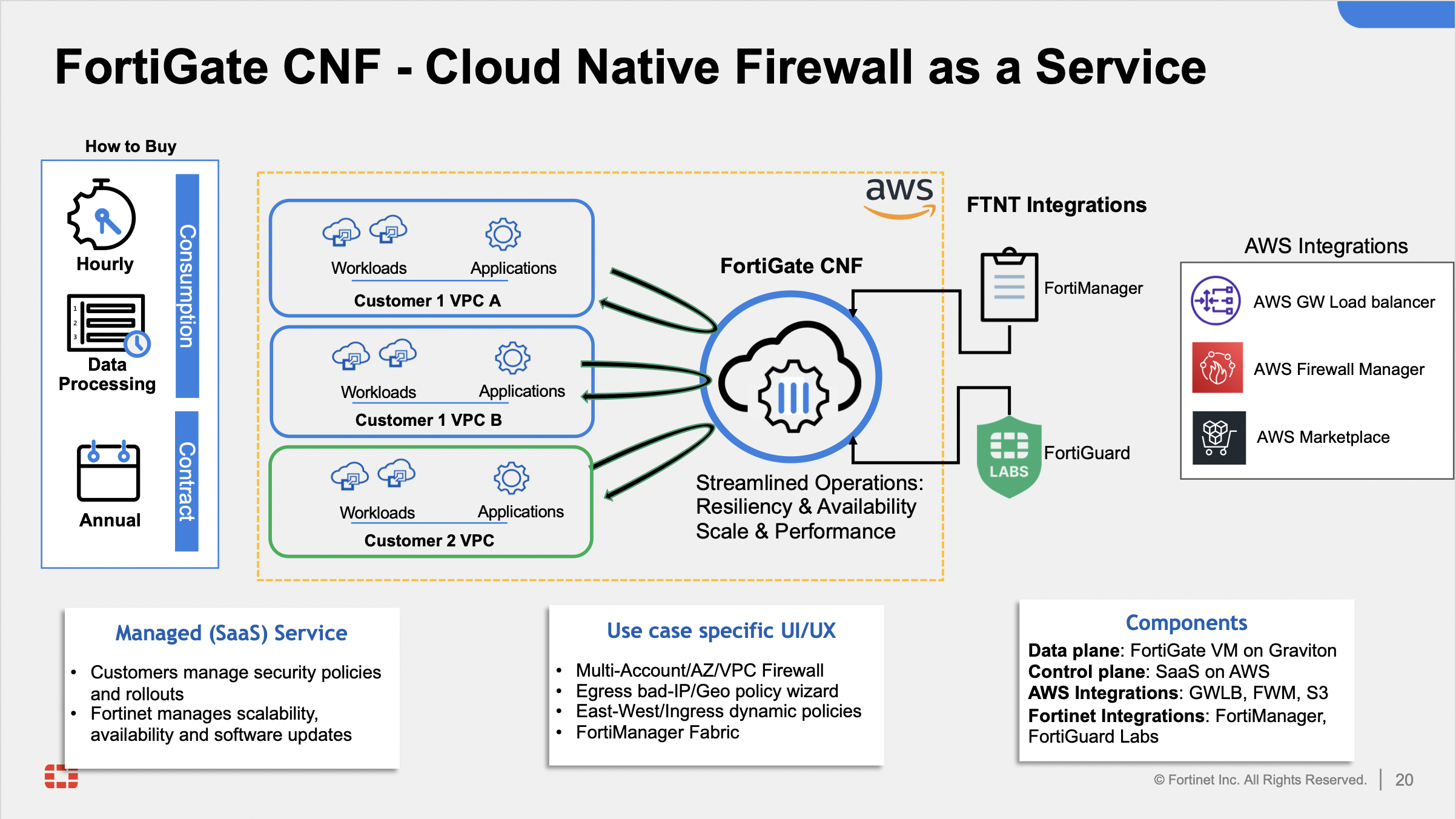
FortiGate CNF is a SaaS offering that on the backend uses FortiGates, AWS GWLB, and GWLB endpoints to intercept customer traffic and inspect this transparently. As part of the deployment process for FortiGate CNF instances, the customer environment will need to implement VPC routing and Ingress Routing at the IGW to intercept the traffic to be inspected.
The FortiGate CNF security stack which includes the AWS GWLB and other components will be deployed in Fortinet managed AWS accounts. The details of the diagram are simply an example of the main components used in FortiGate CNF. This is more to understand what happens when customer traffic is received at our GWLB.

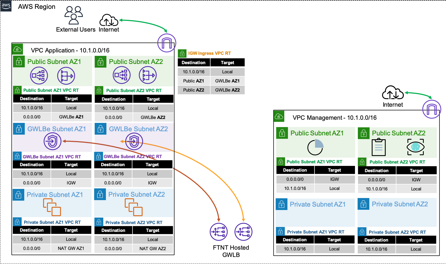
Decentralized designs do not require any routing between the protected VPC and another VPC through TGW. These designs allow simple service insertion with minimal routing changes to the VPC route tables. The yellow numbers show the initial packet flow for a session and how it is routed (using ingress and VPC routes) to the GWLBe endpoint which then sends traffic to the FortiGate CNF stack. The blue numbers show the returned traffic after inspection by the FortiGate CNF stack.
Note
Any subnet where the GWLBe for the FortiGate CNF instance is to be deployed will need to have a specific tag name and value to be seen in the FortiGate CNF portal. Currently this is the tag name fortigatecnf_subnet_type and tag value endpoint.


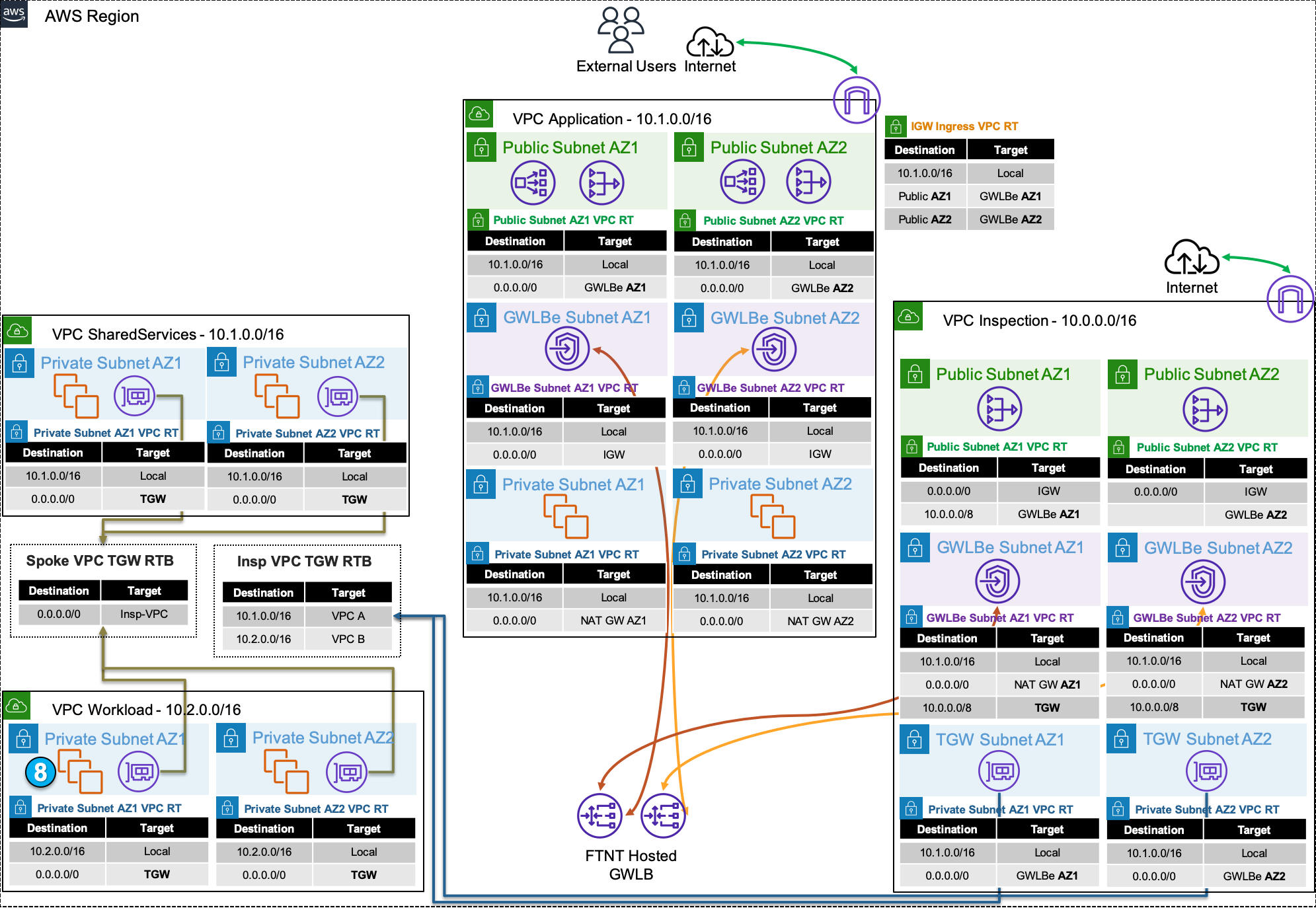
Centralized designs require the use of TGW to provide a simple hub and spoke architecture to inspect traffic. These can simplify east-west, egress, and ingress traffic inspection needs while removing the need for IGWs and NAT Gateways to be deployed in each protected VPC for egress inspection. You can still mix a decentralized architecture to inspect ingress and even egress traffic while leveraging the centralized design for all east-west inspection.
The yellow numbers show the initial packet flow for a session and how it is routed (using ingress, VPC routes, and TGW routes) to the GWLBe which then sends traffic to the FortiGate CNF stack. The blue numbers (east-west) and purple numbers (egress) show the returned traffic after inspection by the FortiGate CNF stack.


For more examples of distributed and centralized models, please reference the examples in the FortiGate CNF Admin Guide.
This concludes this section.
FortiGate CNF Terminology
| Term | Description |
|---|
| CNF Console | The console in which you deploy CNF instances and manage policy sets |
| CNF Instance | A deployment of CNF resources in an auto scale group in the region of your choice |
| Policy Set | The group of FW rules, objects, and security profile groups that are assigned to one or many CNF Instance(s) |
| Security Profile Group | A group of Layer 7 inspection profiles such as Intrision Prevention (IPS), DNS filtering, and known bad IP blocking |


This concludes this section.
Subsections of Workshop Test Traffic
Distributed Ingress
For this traffic flow we will focus on the Application VPC. Distributed ingress is commonly used when there is a need to inspect traffic for a VPC that is directly accessible with an attached IGW and resources with a public Elastic IP (EIP) or behind a public load balancer (ie ALB, NLB, etc). The benefit of this design is that traffic does not need to traverse additional AWS networking components for inspection so each VPC is isolated from others. The caveat to consider is that each VPC would need a directly attached IGW and resources such as load balancers, NAT GWs, etc that have additional cost.

Step 1: An inbound connection starts with an external user initiating a connection to a public resource such as a public NLB. The public NLB has a DNS record that resolves to a public IP for one of the NLB’s Elastic Network Interface (ENI) in either public subnet. The first packet (ie TCP SYN) will then be seen at the IGW attached to the VPC where the public NLB is deployed. Since there is a Ingress route table assigned to the IGW, traffic destined to either public subnet will be sent to the GWLBe endpoint in the same AZ.
Note
The IGW will perform destination NAT to change the public IP of the NLB to the private IP of the NLB ENI.
Step 2: The traffic is received at the GWLBe endpoint which then routes the traffic to the associated GWLB ENI in the same AZ in the managed Fortinet AWS account/VPC. This is done behind the scene using AWS Private Link.
Step 3: The traffic is received at the GWLB ENI and is then encapsulated in a GENEVE tunnel and routed to one of the instances in the FortiGate CNF auto scale group for traffic inspection. Post inspection, if the traffic is allowed, the instance will hairpin the traffic back to the same GWLB ENI over GENEVE. Then the GWLB ENI will hairpin the traffic back to the same GWLBe endpoint.
Step 4: The GWLBe endpoint will then route the inspected traffic to the intrinsic router. The intrinsic router will route traffic directly to the NLB’s ENI as specified in the VPC route table assigned to the subnet.
Step 5: The NLB will send traffic to a healthy target, in either AZ since cross zone load balancing is enabled.
Note
The NLB will perform destination NAT to change the private IP to that of the healthy target.
Step 6: The web server will receive the traffic and respond. The return traffic will flow these steps in reverse.
- To test out this flow navigate to the AWS CloudFormation console and toggle the view nested button to off > then select the stack name > and on the details pane select the outputs tab. You should see the output for URLforApp1. Click on the value for that output to check that App1 is no longer reachable now. Click on the value for the output EncryptedURLforApp1 and you will see the self-signed certificate warning. Once you accept the warning, you will see the test web page.
Note
You are now only allowing HTTPS inbound to your environment that is sourced from a public IP within the United States!


Distributed Egress
For this traffic flow we will focus on the Application VPC. Distributed egress is commonly used when there is a need to inspect traffic for a VPC that has an attached IGW and resources with a public Elastic IP (EIP) or that are behind a NAT GW. The benefit of this design is that traffic does not need to traverse additional AWS networking components for inspection so each VPC is isolated from others. The caveat to consider is that each VPC would need a directly attached IGW and resources such as NAT GWs that have additional cost.

Step 1: An outbound connection starts with a private EC2 instance initiating a connection to a public resource. The first packet (ie TCP SYN) will be routed to the intrinsic router which will route traffic to the NAT GW in the same AZ, as configured in the assigned VPC route table. The EC2 instance has a default route, received via DHCP, that points to the first host IP in the subnet which is the intrinsic router.
Step 2: The traffic is received at the NAT GW ENI which then routes the traffic to the associated GWLBe endpoint in the same AZ, as configured in the assigned VPC route table.
Note
The NAT GW will source NAT the traffic to the private IP assigned to its ENI.
Step 3: The traffic is received at the GWLBe endpoint which then routes the traffic to the associated GWLB ENI in the same AZ in the managed Fortinet AWS account/VPC. This is done behind the scene using AWS Private Link.
Step 4: The traffic is received at the GWLB ENI and is then encapsulated in a GENEVE tunnel and routed to one of the instances in the FortiGate CNF auto scale group for traffic inspection. Post inspection, if the traffic is allowed, the instance will hairpin the traffic back to the same GWLB ENI over GENEVE. Then the GWLB ENI will hairpin the traffic back to the same GWLBe endpoint.
Step 5: The GWLBe endpoint will then route the inspected traffic to the intrinsic router. The intrinsic router will route traffic directly to the IGW as specified in the VPC route table assigned to the subnet.
Note
The IGW will source NAT the traffic to the public EIP assigned to the NAT GW ENI.
Step 6: The destination will receive the traffic and respond. The return traffic will be intercepted at the IGW and routed to the GWLBe endpoint. Then the return traffic follow these steps in reverse.
- To test out this flow navigate to the AWS EC2 console and go to Instances > Instances. Then select either AppInstance and click Connect > EC2 serial console. Copy the instance ID as this will be the username and click connect.


- Login to the instance with the instance ID as the username and
FORTInet123! as the password. Then run the commands below to test traffic:
ping 8.8.8.8
curl http://ipinfo.io
curl https://ipinfo.io
Note
You are now only allowing HTTPS outbound to one FQDN and ICMP to any public IP within the United States!

Centralized Egress
For this traffic flow we will focus on the Shared Services, Workload, and Inspection VPCs. Centralized egress is commonly used when there is a strong desire to control egress traffic through a common set of NAT GWs in an egress or what we call an Inspection VPC. The benefit of this design is that you only need NAT GWs in the Inspection VPC (one per AZ) vs every VPC (one per AZ), which have an hourly cost. The caveat of this design is traffic will traverse additional AWS networking components for inspection (ie TGW, etc) that will have additional cost.

Step 1: An outbound connection starts with a private EC2 instance initiating a connection to a public resource. The first packet (ie TCP SYN) will be routed to the intrinsic router which will route traffic to the TGW attachment in the same AZ, as configured in the assigned VPC route table. The EC2 instance has a default route, received via DHCP, that points to the first host IP in the subnet which is the intrinsic router.
Step 2: The traffic is received at the TGW ENI which then routes the traffic to the Inspection VPC TGW attachment, as configured in the associated Spoke VPC TGW route table.
Step 3: The traffic is received at the TGW ENI in the Inspection VPC which then routes the traffic to the GWLBe endpoint in the same AZ, as configured in the associated VPC route table.
Step 4: The traffic is received at the GWLBe endpoint which then routes the traffic to the associated GWLB ENI in the same AZ in the managed Fortinet AWS account/VPC. This is done behind the scene using AWS Private Link.
Step 5: The traffic is received at the GWLB ENI and is then encapsulated in a GENEVE tunnel and routed to one of the instances in the FortiGate CNF auto scale group for traffic inspection. Post inspection, if the traffic is allowed, the instance will hairpin the traffic back to the same GWLB ENI over GENEVE. Then the GWLB ENI will hairpin the traffic back to the same GWLBe endpoint.
Step 6: The GWLBe endpoint will then route the inspected traffic to the intrinsic router. The intrinsic router will route traffic directly to the NAT GW in the same AZ as specified in the VPC route table assigned to the subnet.
Step 7: The traffic is received at the NAT GW ENI which then routes the traffic to the intrinsic router. The intrinsic router will route traffic directly to the IGW as specified in the VPC route table assigned to the subnet.
Note: The NAT GW will source NAT the traffic to the private IP assigned to its ENI.
Step 8: The destination will receive the traffic and respond. The return traffic will follow these steps in reverse.
Note
The IGW will source NAT the traffic to the public EIP assigned to the NAT GW ENI.
- To test out this flow navigate to the AWS EC2 console and go to Instances > Instances. Then select either WrkInstance and click Connect > EC2 serial console. Copy the instance ID as this will be the username and click connect.


- Login to the instance with the instance ID as the username and
FORTInet123! as the password. Then run the commands below to test traffic:
ping 8.8.8.8
curl http://ipinfo.io
curl https://ipinfo.io
Note
You are now only allowing HTTPS outbound to one FQDN and ICMP to any public IP within the United States!
Question 1: What happens if you try the same test from SSInstance1?
You should be able to access the IPinfo.io site over HTTPS and ping any public IP within the United States.
Question 2: What address objects are allowing this communication to work even though the sdn-group = group3 for this instance?
AppPublicSubnet1 + AppPublicSubnet2. Remember that Dynamic, FQDN, and standard address objects still resolve to IPs. Since the Application-VPC and SharedServices-VPC share the same CIDR the data plane traffic will match on those Address objects.
A solution to this would be to use multiple CNF Instances in a region or expand on your tagging strategy to make the objects be more specific while avoiding using broad subnet CIDR values in the same L4 rule.

Centralized East West
For this traffic flow we will focus on the Shared Services, Workload, and Inspection VPCs. Centralized East West is commonly used when there is need for multiple VPCs in the same region to access common private resources such as a shared services VPC, premise items, or workloads/services in other VPCs. The benefit of this design is that this a flexible but simple way to interconnect many resources in the same region. The caveat of this design is traffic will traverse additional AWS networking components for inspection (ie TGW, etc) that will have additional cost.

Step 1: An outbound connection starts with a private EC2 instance initiating a connection to a public resource. The first packet (ie TCP SYN) will be routed to the intrinsic router which will route traffic to the TGW attachment in the same AZ, as configured in the assigned VPC route table. The EC2 instance has a default route, received via DHCP, that points to the first host IP in the subnet which is the intrinsic router.
Step 2: The traffic is received at the TGW ENI which then routes the traffic to the Inspection VPC TGW attachment, as configured in the associated Spoke VPC TGW route table.
Step 3: The traffic is received at the TGW ENI in the Inspection VPC which then routes the traffic to the GWLBe endpoint in the same AZ, as configured in the associated VPC route table.
Step 4: The traffic is received at the GWLBe endpoint which then routes the traffic to the associated GWLB ENI in the same AZ in the managed Fortinet AWS account/VPC. This is done behind the scene using AWS Private Link.
Step 5: The traffic is received at the GWLB ENI and is then encapsulated in a GENEVE tunnel and routed to one of the instances in the FortiGate CNF auto scale group for traffic inspection. Post inspection, if the traffic is allowed, the instance will hairpin the traffic back to the same GWLB ENI over GENEVE. Then the GWLB ENI will hairpin the traffic back to the same GWLBe endpoint.
Step 6: The GWLBe endpoint will then route the inspected traffic to the intrinsic router. The intrinsic router will route traffic to the TGW attachment in the same AZ as specified in the VPC route table assigned to the subnet.
Step 7: The traffic is received at the TGW ENI which then routes the traffic to the Shared Services VPC TGW attachment, as configured in the associated Inspection VPC TGW route table.
Step 8: The traffic is received at the TGW ENI in the Shared Services VPC which then routes the traffic to the destination, as configured in the associated VPC route table.
- To test out this flow navigate to the AWS EC2 console and go to Instances > Instances. Then select WrkInstance2 and click Connect > EC2 serial console. Copy the instance ID as this will be the username and click connect.


- Login to the instance with the instance ID as the username and
FORTInet123! as the password. Then run the commands below to test traffic:
ping 10.1.2.10
ssh ec2-user@10.1.2.10
curl -k https://10.1.2.10
Note
You are now only allowing HTTPS and RADIUS access between two resourced based on metadata (ie Tags)!
Question 1: What happens if you try the same test from WrkInstance1?
You are able to ping but SS annd HTTPS time out.
Question 2: What tags are allowing this communication to match the dynamic address objects?
For the ProdAPIBackend object, Tag.env=prod AND Tag.app-role=api AND Tag.app-tier=backend. For the ProdAuthBackend object, Tag.env=prod AND Tag.app-role=auth AND Tag.app-tier=backend.