Deploying FortiGate Autoscale Templates in AWS

Deploying FortiGate Autoscale Templates in AWS (build: 11)

Welcome!

AWS Software-Defined Networking (SDN) is elastic, complex, and quite different from traditional on-premise networking. In this workshop you will learn how to deploy FortiGate Firewalls in an elastic autoscale group to protect your AWS workloads deployed in common architecture patterns.

This workshop is intended to help accomplish the following:

  • Learn common AWS networking concepts such as routing traffic in and out of VPCs for various traffic flows
  • Use AWS Cloudshell and Terraform to deploy a Fortigate autoscale group in a usable demo environment
  • Interact with a FortiGate autoscale group build security policy sets, and deploy them
  • Test traffic flows in an example environment and use a FortiGate autoscale group to control traffic flows
  • Deploy a FortiGate autoscale group into an existing customer environment.
Version:
Last updated: Thu, May 22, 2025 22:28:28 UTC
Copyright© 2025 Fortinet, Inc. All rights reserved. Fortinet®, FortiGate®, FortiCare® and FortiGuard®, and certain other marks are registered trademarks of Fortinet, Inc., and other Fortinet names herein may also be registered and/or common law trademarks of Fortinet. All other product or company names may be trademarks of their respective owners. Performance and other metrics contained herein were attained in internal lab tests under ideal conditions, and actual performance and other results may vary. Network variables, different network environments and other conditions may affect performance results. Nothing herein represents any binding commitment by Fortinet, and Fortinet disclaims all warranties, whether express or implied, except to the extent Fortinet enters a binding written contract, signed by Fortinet’s General Counsel, with a purchaser that expressly warrants that the identified product will perform according to certain expressly-identified performance metrics and, in such event, only the specific performance metrics expressly identified in such binding written contract shall be binding on Fortinet. For absolute clarity, any such warranty will be limited to performance in the same ideal conditions as in Fortinet’s internal lab tests. Fortinet disclaims in full any covenants, representations, and guarantees pursuant hereto, whether express or implied. Fortinet reserves the right to change, modify, transfer, or otherwise revise this publication without notice, and the most current version of the publication shall be applicable.

Subsections of Deploying FortiGate Autoscale Templates in AWS

Introduction

How to Demo and Sell FortiGate Autoscale in AWS

Welcome!

In this TEC Recipe, you will learn how to deploy a FortiGate autoscale group using the templates found in this github repository: https://github.com/fortinetdev/terraform-aws-cloud-modules.git.

Fortinet customers can use this service to protect AWS workloads deployed in the cloud. Later sections in the TEC Recipe will demonstrate the use of the distributed egress architecture to protect ingress and egress traffic in a existing customer workload vpc.

This TEC Recipe is intended to help accomplish the following:

  • Learn common AWS networking concepts such as routing traffic in and out of VPCs for various traffic flows
  • Use AWS Cloudshell and Terraform to deploy a demo environment
  • Interact with FortiGate GUI and CLI, to build security policy sets and deploy them
  • Test a couple of traffic flows in an example environment and use FortiGate deployed as an autoscale group to control traffic
  • Deploy a FortiGate Autoscale Group into an existing customer environment.

Learning Objectives

At the end of this TEC Recipe, you will complete the following objectives:

  • Understand AWS Networking Concepts (10 minutes)
  • Understand AWS Common Architecture Patterns (10 minutes)
  • Use AWS Cloudshell and Terraform to deploy a demo environment (10 minutes)
  • Deploy a FortiGate Autoscale Group to control a distributed egress architecture (20 minutes)
  • Create a policy set and apply it to a FortiGate Autoscale Group (10 minutes)
  • Test traffic flows (distributed ingress + egress) (20 minutes)
  • Use terraform to destroy the fortigate autoscale group (25 minutes)
  • Use terraform to destroy the resources for the distributed egress architecture (10 minutes)

TEC Recipe Components

These are the AWS and Fortinet components that will be used during this workshop:

  • AWS Marketplace
  • AWS CloudShell
  • Hashicorp Terraform Templates (Infrastructure as Code, IaC)
  • AWS SDN (AWS intrinsic router and route tables in a VPC)
  • AWS Gateway Load Balancer (GWLB) and associated endpoints
  • AWS EC2 Instances (Ubuntu Linux OS)
  • A hybrid licensed Fortigate Autoscale Group. (BYOL for perpetual instances and PAYGO for autoscale instances)

AWS Reference Architecture Diagram

This is the architecture and environment that will be used in the workshop.

  • With AWS networking, there are several ways to organize your AWS architecture to take advantage of FortiGate Autoscale Group traffic inspection. The important point to know is that as long as the traffic flow has a symmetrical routing path (for forward and reverse flows), the architecture will work.
  • This diagram will highlight distrubuted designs that are common architecture patterns for securing traffic flows.
  • Distributed Ingress + Egress

Reference Diagram for the Workshop

  • Distributed Ingress + Egress

  • Routes and Hops

  • This diagram is showing TGW subnets in the security VPC. These subnets are not used in this workshop, but TGW subnets are used in a centralized egress architecture. The TGW subnnets are where the TGW Attachments are associated in this architecture. Since the same Fortigate Autoscale Group can be used to inspect traffic from both architectures simultaneously, these subnets are still included in the diagram.

Workshop Prerequisites

In this section, we will introduce the prerequisites for this workshop.

To complete the workshop, you will need an understanding of the following concepts and access to the following resources:

  • An AWS Account with access to the us-west-2 region (Oregon)
  • Two ITF’d FGVMU (Fortigate VM Unlimited) licenses for the BYOL portion of the hybrid licensing model.
  • The AWS_ACCESS_KEY and AWS_SECRET_ACCESS_KEY for your AWS Account.
  • You will need at least 5 Elastic IPs in your AWS Account for the us-west-2 region. It is recommended to ask AWS to up the limit to 10.
  • AWS Networking Concepts
    • VPCs
    • Availability Zones (AZ’s)
    • Regions
    • Subnets
    • Route Tables
    • Internet Gateways (IGW)
    • NAT Gateways (NATGW)
    • Elastic IP Addresses (EIP)
    • Security Groups (SG)
    • AWS Gateway Load Balancer (GWLB)
    • AWS Lambda
    • AWS Autoscale
    • AWS Cloudwatch
  • AWS Common Architecture Patterns
    • Distributed Ingress + Egress
    • Centralized Egress + East-West

Subsections of Workshop Prerequisites

Workshop Logistics

Accessing an AWS environment

For the FortiGate Autoscale Tec Recipe, you will need the following:

  • AWS sign in link
  • IAM User w/ console access
  • Password for the IAM User
  • Two properly sized ITF’d BYOL licenses for Fortigate VM (recommend unlimited CPUs to avoid sizing confusion)

When you first login you will see the Console Home page.

Use the Search Box at the top to search for services such as EC2, VPC, Cloud Shell, etc.

When the results pop up, right click the name of the service and open the desired console in a new tab. This makes navigation easier.

AWS Networking Concepts

Before diving into the reference architecture for this workshop, let’s review core AWS networking concepts.

AWS Virtual Private Cloud (VPC) is a logically isolated section of the AWS Cloud where you can launch AWS resources in a virtual network that you define. You have complete control over your virtual networking environment, including selection of your own IP address range, creation of subnets, and configuration of route tables and network gateways.

Availability zones (AZ) are multiple, isolated locations within each Region that have independent power, cooling, physical security, etc. A VPC spans all of the AZs in the Region.

Region, is a collection of multiple regional AZs in a geographic location. The collection of AZs in the same region are all interconnected via redundant, ultra-low-latency networks.

All subnets within a VPC are able to reach each other with the default or intrinsic router within the VPC. All resources in a subnet use the intrinsic router (1st host IP in each subnet) as the default gateway. Each subnet must be associated with a VPC route table, which specifies the allowed routes for outbound traffic leaving the subnet.

An Internet Gateway (IGW) is a horizontally scaled, redundant, and highly available VPC component that allows communication between instances in your VPC and the internet. It therefore imposes no availability risks or bandwidth constraints on your network traffic.

AWS NAT Gateway (NAT GW) is a Network Address Translation (NAT) service. You can use a NAT gateway so that instances in a private subnet can connect to services outside your VPC but external services cannot initiate a connection with those instances.

AWS Transit Gateway (TGW) is a highly scalable cloud router that connects your VPCs in the same region to each other, to on-premise networks, and even to the internet through one hub. With the use of multiple route tables for a single TGW, you can design hub and spoke routing for traffic inspection and enforcement of security policy across multiple VPCs.

AWS (Gateway Load Balancer (GWLB) is a transparent network gateway that distributes traffic (in a 3/5 tuple flow aware manner) to a fleet of virtual appliances for inspection. This is a regional load balancer that uses GWLB endpoints (GWLBe) to securely intercept data plane traffic within consumer VPCs in the same region.

In this workshop we will use all these components to test FortiGate Autoscale in an enterprise design.

AWS Common Architecture Patterns

While there are many ways to organize your infrastructure, there are two main ways to design your networking when using GWLB:

  • centralized
  • distributed.

We will discuss this further below.

FortiGate Autoscale uses FortiGates on the backend and routes all traffic through the Fortigates for traffic inspection. AWS GWLB, and GWLB endpoints to intercept customer traffic and inspect this traffic transparently. As part of the deployment process for FortiGate Autoscale instances, the customer environment will need to implement VPC and ingress routing at the IGW to intercept the traffic to be inspected.

The FortiGate Autoscale security stack, which includes the AWS GWLB and other components, will be deployed in a centralized inspection VPC. The details of the diagram are simply an example of the main components used in FortiGate Security VPC Autoscale stack.

The following diagrams and paragraphs will explain what happens when customer traffic is received at the FortiGate Autoscale GWLB.

Decentralized designs do not require any routing between the protected VPC and another VPC through TGW. These designs allow simple service insertion with minimal routing changes to the VPC route table. The yellow numbers show the initial packet flow for a session and how it is routed (using ingress and VPC routes) to the GWLBe endpoint which then sends traffic to the FortiGate CNF stack. The blue numbers show the returned traffic after inspection by the FortiGate CNF stack.

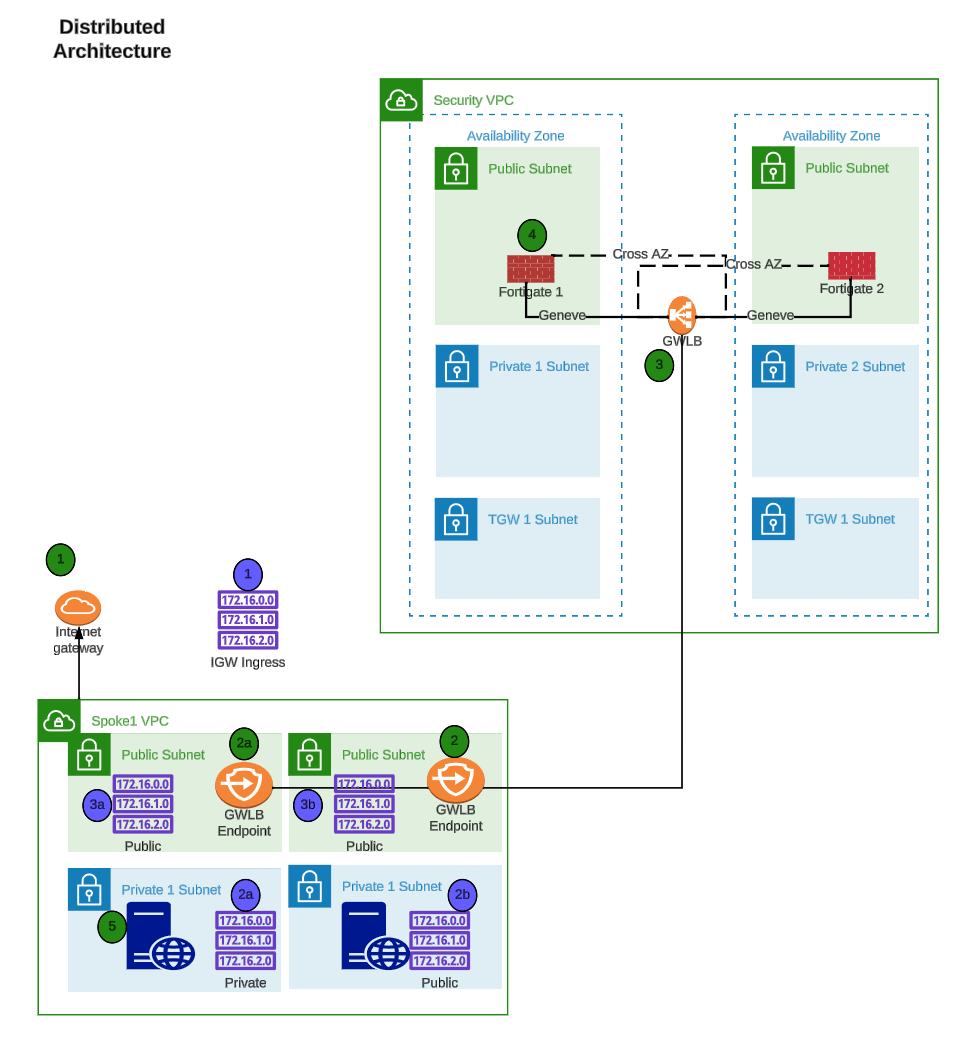
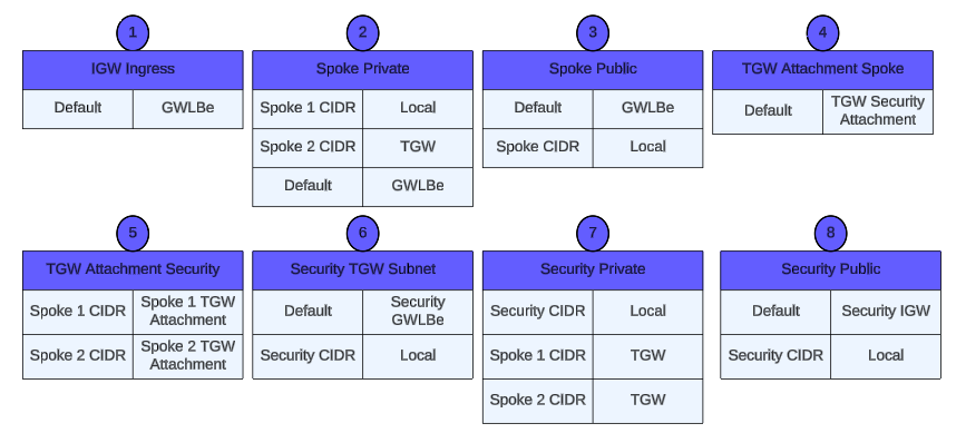
Centralized designs require the use of TGW to provide a simple hub and spoke architecture to inspect traffic. These can simplify east-west and egress traffic inspection needs while removing the need for IGWs and NAT Gateways to be deployed in each protected VPC for egress inspection. You can still mix a decentralized architecture to inspect ingress and even egress traffic while leveraging the centralized design for all east-west inspection.

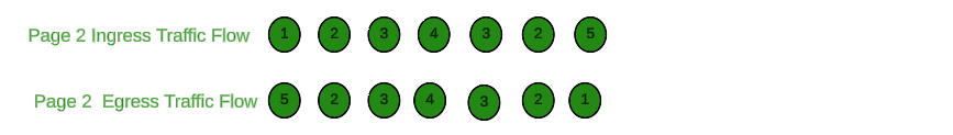
The yellow numbers show the initial packet flow for a session and how it is routed (using ingress, VPC routes, and TGW routes) to the GWLBe which then sends traffic to the FortiGate Autoscale stack. The blue numbers (east-west) and purple numbers (egress) show the returned traffic after inspection by the FortiGate Autoscale Group.

Terraform Install and Deployment

In this section, we will use AWS Cloudshell to install Terraform and deploy the Terraform templates that will be used to deploy the demo environment. AWS Cloudshell is a browser-based shell that is pre-configured to interact with AWS services. It is a great way to get started with AWS CLI and Terraform without having to install anything on your local machine. We will install Terraform on AWS Cloudshell and then use it to deploy the demo environment and Terraform will use tfenv to control the version of Terraform that is installed. AWS Cloudshell has a 1 GB disk storage limitation. This will prevent us from deploying larger templates or multiple templates from the same Cloudshell instance. For production use, it is recommended to install Terraform on your local machine and/or use it in a CI/CD pipeline to manage production environments.

Subsections of Terraform Install and Deployment

Task 1: Install Terraform in AWS Cloudshell

  • Log into your AWS account and navigate to the Console Home.
  • Click on the AWS CloudShell icon on the console navigation bar

  • We are going to use the Terraform Version Manager to help install Terraform

  • Clone the Terraform Version Manager repository

    git clone https://github.com/tfutils/tfenv.git ~/.tfenv

  • Make a new directory called ~/bin

    mkdir ~/bin

  • Make a symlink for tfenv/bin/* scripts into the path ~/bin

    ln -s ~/.tfenv/bin/* ~/bin

  • With the Terraform Version Manager installed, we can now install Terraform.

    tfenv install

  • This will install the latest version of Terraform for you. Take note of the installed version of terrform. In this case, the default version is 1.5.3.

  • To make this version the default version, use the following commmand

    tfenv use 1.5.3

Info

Note: The current version of terraform changes as newer patches are released. Just use the latest version of terraform for this workshop.

  • Verify you are using the proper version of terraform

    terraform -v

  • This concludes this section.

Task 2: Create Distributed Workload VPC using Terraform in AWS Cloudshell

Info

Note: Make sure you are running this workshop in the intended region. The defaults are configured to run this workshop in us-west-2 (Oregon). Make sure your management console is running in us-west-2 (Oregon), unless you intend to run the workshop in a different supported region.

  • Click on the AWS CloudShell icon on the console navigation bar

  • Clone a repository that uses terraform to create a distributed ingress workload vpc

    git clone https://github.com/FortinetCloudCSE/FortiGate-AWS-Autoscale-TEC-Workshop.git

  • Change directory into the newly created repository for distributed_ingress_nlb

    cd FortiGate-AWS-Autoscale-TEC-Workshop/terraform/distributed_ingress_nlb

  • Copy the terraform.tfvars.example to terraform.tfvars

    cp terraform.tfvars.example terraform.tfvars

  • Edit the terraform.tfvars file and insert the name of a valid keypair in the keypair variable name and save the file
Info

Note: Examples of preinstalled editors in the Cloudshell environment include: vi, vim, nano

Info

Note: AWS Keypairs are only valid within a specific region. To find the keypairs you have in the region you are executing the lab in, check the list of keypairs here: AWS Console->EC2->Network & Security->keypairs. This workshop is pre-configured in the terraform.tfvars to run in the us-west-2 (Oregon) region.

Info

Note: You may change the default region in the terraform.tfvars file to another FortiGate supported region if you don’t have a valid keypair in that region and you don’t want to create one for this workshop.

  • The NLB is disabled by default in this workshop. We are not using the NLB and it requires two additional Elastic IPs. If you would like to enable the nlb and test traffic flows through the NLB, enable it here.

  • Use the “terraform init” command to initialize the template and download the providers

    terraform init

  • Use “terraform apply –auto-approve” command to build the vpc. This command takes about 5 minutes to complete.

terraform apply --auto-approve

  • When the command completes, verify “Apply Complete” and valid output statements.
    • Make note of the Web Url (red arrow) for each instance and for the NLB that load balances between the Availability Zones.
    • Make note of the ssh command (yellow arrow) you should use to ssh into the linux instances.
    • Make note of the spk_vpc section of the output. This will be used as input to the autoscale templates. This defines the vpc id of the distributed workload vpc and the subnet_ids for the gwlb endpoints.
    • Bring up a local browser and try to access the Web Url.
    • Copy the “Outputs” section to a scratchpad. We will use this info throughout this workshop.

The network diagram for the distributed ingress vpc looks like this:

  • This concludes this section.

IaC Discussion Points

Discussion Points During a Demo - Chapter 3

Fortinet provides a large library of infrastructure as code (IaC) templates to deploy baseline and iterate POC and production environments in public cloud. IaC support includes Terraform, Ansible, and cloud-specific services such as Azure ARM, AWS Cloudformation, and Google Deployment templates. Terraform Providers are available for several Fortinet products to insert and iterate running configuration.

For more information, review the following:

Advantages of Using AWS CloudShell for Deployment

AWS CloudShell is a browser-based shell that makes it easy to securely manage, explore, and interact with your AWS resources. CloudShell is pre-authenticated with your console credentials and common development and operations tools are pre-installed. CloudShell is available in all commercial AWS regions at no additional cost and provides an environment with preconfigured CLI tools and access to AWS services. CloudShell provides a temporary 1 GB storage volume that is deleted after 120 minutes of inactivity. CloudShell is a convenient method to deploy IaC templates for demonstrations and quick deployments.

Alternative Methods of using Terraform in Production Environments

AWS Cloudshell is a nice environment for deploying demo environments. However, for production environments, it is recommended to use a local workstation or a CI/CD pipeline. If your customer is asking about how to deploy Terraform in production, you can point them to the following resources:

Be sure to point out that the Fortinet Terraform templates are free to use and modify. These templates are designed to illustrate reference architectures in a demo environment only and may require modification to meet production requirements.

Key questions during your demo

When giving this TEC Workshop as a demo, the following questions will provide a basis for next steps and future meetings:

  • Has your organization standardized on an IaC tool-set for infrastructure provisioning and iteration?
  • How are the responsibilities for infrastructure assigned? Does cloud network fall under a DevOps, Cloud Networking, or Application Delivery team, as examples?
  • What is organizations view on how IaC can improve workflows?
  • Is workflow automation in cloud and cross-organizational collaboration important within your cloud business?

Protect the Workload VPC with Security Groups

This section will configure security groups to protect a few of the critical resources in the demo environment. Security Groups are stateful firewalls that control traffic to and from AWS resources. Security Groups are applied to AWS resources such as EC2 instances, RDS instances, and Elastic Load Balancers. This type of security is limited to layer 4 only and is not able to inspect the contents of the traffic. For this reason, it is recommended to use Security Groups in conjunction with a FortiGate Security Policy to provide layer 7 inspection and advanced security features.

Info

Note: If you do not limit access to your ec2 instances on SSH and HTTPS, you may get a Guard Duty warning letter like the one pictured below.

Subsections of Protect the Workload VPC with Security Groups

Task 3: Protect the Workload VPC with Security Group Rules

The network diagram for the distributed ingress vpc looks like this:

On deployment, the ec2 instances deployed in the private subnet of the distributed ingress workload vpc have open access to SSH and HTTPS.

  • Let’s take a look at the security group for the linux instance.
    • From Console Home, click on EC2
    • From EC2, click on Instances (running)
    • Choose the instance in AZ1
    • Click on the security tab for the instance
    • Click on the link to the security group

  • On this screen, we can see that we are allowing SSH (tcp port 22) and HTTP (tcp port 80) from any IPv4 address. The instance is protected from login by the ssh keypair, but let’s tighten the security up using the security group to prevent random access to the Apache server.
    • Click on “Edit Inbound Rules” (yellow arrow)

  • Click on the “Source” dropdown and change “Anywhere-IPv4” to “My IP” for the Inbound HTTP and Inbound SSH.
  • Change the description from Anywhere to My IP
  • Click “Save Rules”

  • Now we have security rules to access our linux instances via SSH and HTTP from our Public IP.

  • We also have security rules that allow HTTP and SSH via the NLB to have access to the linux instances. The NLB has a Public IP in each AZ. This allows us to access the backend servers through the NLB and the access will be load balanced across each AZ.

  • Lookup the “Public IP” associated with each linux instance and bring up a browser to verify connectivity. You should see a slightly modified Default Apache2 Page that also shows the AZ of the response linux instance.

  • This was a small demonstration on managing security policy with security groups. A bit tedious don’t you think? Now let’s deploy a Fortigate Security Policy instance and manage security policy with a Next Generation Firewall.

  • This concludes this section.

Managing Security with AWS Security Groups - Discussion Points

Discussion Points During a Demo - Chapter 3

Key reasons for using a Next Generation Firewall in the cloud:

  • AWS Security Groups are static and do not provide dynamic security policies that can keep up with the dynamic nature of cloud infrastructure.
  • Building dynamic policies with AWS Security Groups is a manual process that is not scalable.
  • AWS Security Groups do not use threat intelligence to block known bad IP addresses and new or unknown threat vectors like a Next Generation Firewall does.
  • Updating AWS Security Groups across a large deployment is prone to error and omission.
  • AWS Security Groups are not managed through a single pane of glass across multi-cloud and on-premises environments.

Key questions during your demo

When giving this TEC Workshop as a demo, the following questions will point out that AWS Security Groups are not dynamic enough to keep up with changing cloud infrastructure and do not inspect the traffic at layers 4-7 like a Next Generation Firewall does:

  • Do you plan to provide deep inspection of traffic in your cloud environment? Security Groups are limited to layer 4 inspection only. FortiGate firewalls can apply UTM inspection profiles to traffic flows and protect against a wide range of new or unknown threat vectors.
  • Do you plan to provide dynamic security policies that can keep up with the dynamic nature of cloud infrastructure? Security Groups are static and do not provide dynamic security policies. FortiGate objects can be dynamically built and updated based on tags and other attributes that scales with a changing cloud infrastructure.
  • Do you plan to provide a single pane of glass for security policy management across your cloud and on-premises environments? Security Groups are limited to AWS only and do not provide a single pane of glass for security policy management across multi-cloud and on-premises environments.

Deploy a standard configuration FortiGate Autoscale group into the existing distributed egress workload vpc

This section will deploy a standard configuration FortiGate Autoscale group using Fortinet Autoscale Terraform templates. These templates will create a security VPC and associated subnets, route tables, autoscale groups, and a single FortiGate Primary instance.The template will also deploy Gateway Load Balancer endoints into the specified subnets of the workload VPC. The security policy will be created on the single “Primary” FortiGate instance using the FortiGate GUI.

Subsections of Deploy a standard configuration FortiGate Autoscale group into the existing distributed egress workload vpc

Task 4: Deploy a standard configuration FortiGate Autoscale group

  • This task will deploy a FortiGate Autoscale group and install gateway load balancer endpoints (GWLBe) in the appropriate subnets of the distributed ingress workload vpc. Unfortunately, we will not be able to deploy the FortiGate Autoscale Group template from within AWS Cloudshell due to the 1GB disk space limitation of Cloudshell. If you take a look at the network diagram of the distributed ingress workload vpc, you will see that a linux ec2 instance was deployed in AZ1 with a public EIP address. This public IP address should be in the output of the template and you should have this saved in your scratchpad that was saved in the previous task. This ec2 instance is preconfigured with terraform and we will use this instance to clone and deploy the FortiGate Autoscale Group.

  • Using a slightly modified command in your scratchpad, let’s scp copy our licenses to the linux instance in az1. We will use these licenses to attach to the byol instances used in the deployment. This workshop will use two licenses. We will move these licenses to the appropriate place in a later step.

    • Locate your licenses and put them in your current directory.
    • Substitute the keypair and public IP into the command.

    scp -i <keypair> *.lic ubuntu@<public-ip>:~

  • ssh into the Linux instance in AZ1 using the command in your scratchpad.

    ssh -i <keypair> ubuntu@<public-ip>

  • There are a number of tasks that take place due to the userdata template found in the cloudshell repo we just deployed. The details can be found in FortiGate-AWS-Autoscale-TEC-Workshop/terraform/distributed_ingress_nlb/config_templates/web-userdata.tpl. Before continuing with the autoscale deployment, we need to allow the userdata to complete. Monitor the output in /var/log/cloud-init-output.log. When it is finished, you should see the output stop with the following message.

  • When the userdata configuration is complete, use ^C to exit from the “tail -f” command.

    tail -f /var/log/cloud-init-output.log

  • First task is to provide the ec2 instance with your AWS account credentials. This will provide the necessary permissions to run the autoscale terraform templates.

    • from the command line, run the aws configure and enter your access key, access secret, default region, and preferred output (text, json).

    aws configure

  • The ec2 instance has been pre-configured to export your AWS credentials into the login environment variables. If you would like to investigate the specifics, see the web-userdata.tpl file in the config_templates directory of the templates we deployed in task 2. In order to export the credentials, we will need to logout and login again. Please check the values for the proper credentials.

    exit

    ssh -i <keypair> ubuntu@<public-ip>

    env

  • Clone build 11 of the autoscale templates repository that uses terraform to create a distributed ingress workload vpc.

    git clone https://github.com/fortinetdev/terraform-aws-cloud-modules.git

  • Change directory into the newly created repository and move to the examples/spk_gwlb_asg_fgt_gwlb_igw directory. This directory will deploy a Fortigate Autoscale group with a Gateway Load Balancer and gateway load balancer endpoints in the appropriate subnets of the distributed ingress workload vpc.

    cd terraform-aws-cloud-modules/examples/spk_gwlb_asg_fgt_gwlb_igw

  • Copy the terraform.tfvars.example to terraform.tfvars

    cp terraform.tfvars.txt terraform.tfvars

  • Edit the terraform.tfvars file. If you are not using AWS Cloudshell, then I recommend exporting your AWS credentials into your environment and not hard-coding your credentials into the terraform.tfvars file. You can find more information here: https://docs.aws.amazon.com/cli/latest/userguide/cli-configure-envvars.html. Luckily, the workshop already setup the ~/.bashrc to export the variables into your enviornment and you don’t have to do anything.
Tip

Note: You can find more information on exporting your AWS credentials into your environment here: https://docs.aws.amazon.com/cli/latest/userguide/cli-configure-envars.html

Info

Note: Examples of preinstalled editors in the Cloudshell environment include: vi, vim, nano

Info

Note: This task will create a Fortigate Autoscale deployment suitable for a customer demo environment.

Info
  • This workshop will assume your access_key and secret_key are already exported into your environment. Remove the “access_key” and “secret_key” lines and fill in the “region” you intend to use for your deployment.

  • Fill in the cidr_block you want to use for the inspection VPC.

  • Fill in the cidr_block you want to use for each spoke_vpc. Create the spoke_cidr_list as a terraform list.

  • Create a terraform list for the set of availability_zones you want to use.

    Info

    Note: us-west-2b does not support the service endpoint used by these templates. Use us-west-2c instead

  • Fill in the desired fgt_intf_mode. 1-arm mode uses a single Fortigate ENI and hairpins the traffic in and out of the same ENI. 2-arm mode uses two Fortigate ENIs and allows for a more traditional routing configuration via a public and private interface.

  • This workshop will use the 2-arm mode.

  • Each Fortigate Autoscale deployment using standard BYOL and PayGo licensing will create 2 autosclale groups. The BYOL autoscale group will use the BYOL licenses found in the license directory. If more instances are needed to handle the load on the autoscale group, Fortigate Autoscale will scale-out using PayGo instances if all BYOL licenses are consumed. Lets fill in the BYOL section of the template.

  • Fill in the byol section with values for the highlighted variables:

    • template_name = anything
    • fgt_version = desired fortios version
    • license_type = leave as byol
    • fgt_password = desired fortigate password when logging into the fortigate
    • keypair_name = keypair used for passwordless login
    • lic_folder_path = path to Fortigate byol licenses
    • asg_max_size = maximum number of instances in the autoscale group
    • asg_min_size = minimum number of instances in the autoscale group
    • asg_desired_capacity = desired number of instances in the autoscale group (we will leave desired at one until we get everything configured)
    • user_conf_file_path provides configuration cli to preconfigure the fortigates. Leave this variable as-is. The workshop included a pre-confiured fgt_conf.conf file in the home directory. We will copy the pre-made fgt_config.conf file into place in a few steps
    • leave the rest of the variables as-is

  • Fill in the on_demand (on_demand) section with values for the highlighted variables:

    • template_name = anything

    • fgt_version = desired fortios version

    • license_type = leave as on-demand

    • fgt_password = desired fortigate password when logging into the fortigate

    • keypair_name = keypair used for passwordless login

    • asg_max_size = maximum number of on-demand instances in the autoscale group

    • asg_min_size = Leave minimum set to 0. We want paygo autoscale to scale-in back to 0 if the instances are not needed.

    • asg_desired_capacity = Leave desired set to 0. We want on-demand to only scale as a result of an autoscale event.

    • user_conf_file_path provides configuration cli to preconfigure the fortigates. Leave this variable as-is. The workshop included a pre-confiured fgt_conf.conf file in the home directory. We will copy the pre-made fgt_config.conf file into place in a few steps

    • leave the rest of the variables as-is

  • The scale policies control the scaling of the autoscale groups. The scale policies are based on the average CPU utilization of the autoscale group. The scale policies are set to scale out when the average CPU utilization is greater than 80% and scale in when the average CPU utilization is less than 30%. The scale policies are set to scale out and in by 1 instance. This workshop will leave the scaling policies as is.

  • Set enable_cross_zone_load_balancing to true. This will allow the Gateway Load Balancer to distribute traffic across all instances in all availability zones.

  • Copy the spk_vpc section from your scratchpad and paste it into the tfvars file.

  • Set general_tags to anything you like. Each resource created by the template will have these tags.

  • As you can see in the example tfvars file, there are many options (commented out) for configuring the route tables in the security vpc and the spoke vpcs. However, these will not work for the distributed_ingress VPC because the original template created the necessary routes to make this a “working” vpc. The autoscale template is not able to “modify” the existing routes. Therefore, this workshop will only deploy the gwlb endpoints via the template and we will manually modify the route tables in a later task.

  • Paste the spk_vpc definition from the output of the previous template (output in scratchpad). This was added to the distributed template to make sure the proper format is used. This spk_vpc definition will deploy the gwlb endpoints into the specified vpc_id and place the gwlbe’s into the specified subnets. These are the subnets labeled gwlbe-az1 and gwlbe-az2.

Info

Note: Monitor this mantis for updates on the ability to automatically modify the necessary routes into the workload vpc: https://mantis.fortinet.com/bug_view_page.php?bug_id=1021311

  • Now copy the fgt_config.conf file we want to use into the repository. Feel free to take a look to see what is preconfigured.

  • Now copy the license files you copied over and put them in license directory.

  • Remove the example license file “license1.lic”. The autoscale lambda function will mistakenly attach this file as a valid license if you leave it in the directory.

    cp ~/fgt_config.conf ./fgt_config.conf

    mv ~/*.lic ./license

    rm license/license1.lic

  • Use the “terraform init” command to initialize the template and download the providers

    terraform init

  • Use “terraform apply –auto-approve” command to build the vpc. This command takes about 10-12 minutes to complete.

terraform apply --auto-approve

  • When the command completes, verify “Apply Complete” and valid output statements.

  • This concludes this section.

Task 5: Modify VPC Route Tables to direct North-South Traffic to GWLBe's for inspection

  • The initial deployed terraform template is a working deployment with ingress traffic NAT’d to all of the EIP’s by the IGW. Egress traffic is sent to the IGW by a default route in each route table pointing to the IGW. The initial deployment will not have any security, except for the security groups. This initial template design is depicted in this picture:

  • The default VPC route tables route the traffic directed at one of the EIP’s into the VPC as local traffic. In other words, if the traffic is directed at an Elastic IP on the NLB or one associated with a Linux instance, the IGW will NAT the traffic to the private IP associated with the EIP public IP. For egress traffic, all VPC route tables have a default route that points to the IGW.

  • Once we deploy a FortiGate Autoscale Group and the associated endpoints, we will need to modify the Spoke VPC route tables for the FortiGate instances to inspect the traffic. To redirect the ingress traffic, we need a few route table entries added to the IGW Ingress Route Table. To redirect egress traffic, change the default route in the private route table. The modified design will look like this:

Info

Note: Changes to the route tables are in RED.

Info

Note: If you don’t have Elastic IP’s associated with each Linux Instance, then the last two entries in the IGW Route Table are unnecessary.

  • The tricky part here is to make sure you point the routes at the correct GWLB Endpoint, i.e. the endpoint in the same AZ as the route table that you are modifying. If you don’t do this correctly, you will create routes that push the traffic across AZ’s and add cost to the deployment. Watch for the hints below to assist with this.

  • Log into your AWS account and navigate to the Console Home.

  • Click on the VPC icon

  • First, we need to understand which GWLB Endpoint is deployed in each AZ. To do this, click on “Endpoints” in the left pane.

  • Then choose one of the Endpoints and click subnets in the lower window.

  • From this screen, you can see the subnet id where the Endpoint is deployed. You have a few options here.

    • You could navigate to the subnet tab on the left navigation pane and check which AZ that subnet is in using the subnet id.
    • You might notice that the IP address is 10.0.0.180. This IP address may change on different deployments, but the subnet should stay the same. If you check the network diagram above, you can see that the 10.0.0.0/24 CIDR is in AZ1.
    • In this case, I included the AZ in the name of the name of the subnet “asg-dist-lab-workload-az1” in the terraform that deployed the workshop VPC. It’s a useful hint in this case, but that may not be true in other VPC environments.
    • Nevertheless, this endpoint (vpce-xxxxcee0) is deployed in AZ1 and (vpce-xxxxd9f3) is deployed in AZ2.
    • You might want to add this info to your scratchpad.
  • Now let’s modify the route tables. Click on “Route tables” in the left pane

  • Highlight the IGW Ingress Route table named “asg-dist-lab-igw-rt”.
  • Click on the “Routes” tab at the bottom.
  • Click on “Edit routes”.

  • We could just change the full VPC CIDR Route and send the traffic to one of the GWLB Endpoints we created earlier. That would redirect all ingress traffic to one AZ or the other. But that would create cross AZ traffic and that would drive up the cost of the deployment. Don’t do this!

  • Instead, let’s create an entry for each VPC subnet that we want to redirect and send it to the GWLBe in the same AZ. In this example, we have an NLB with a subnet mapping in the Public Subnet in each AZ. We can see this by looking at the Network Mapping associated with the NLB.

  • So lets add an IGW Ingress Route Table entry for each Public Subnet CIDR and send that traffic to the GWLBe in the same AZ.
    • Remember, 10.0.0.0/24 is in AZ1 and the VPC Endpoint for AZ1 is vpce-xxxxcee0
    • 10.0.3.0/24 is in AZ2 and the VPC Endpoint for AZ2 is vpce-xxxxd9f3

  • If we want the firewall to inspect traffic going to the EIP associated with the Linux instances, we need to add a similar route entry. The Linux instances are in the private subnet. Those CIDR’s are 10.0.2.0/24 and 10.0.5.0/24. So add route table entries for those CIDR’s.
  • Click “Save changes”
  • These changes redirect ingress traffic. Now lets redirect egress traffic.
Info

Note: Disregard the actual VPC Endpoint ID’s used in the images. The workshop images were collected over multiple deployments and the VPCE ID’s may have changed. We just want to make sure AZ Affinity is preserved when adding the routes.

  • In this example, all the traffic goes to the linux instances and those instances are in the private subnets. The ingress traffic can be directed at the NLB subnet mappings or directly to the EIPs on the Linux instances. To have the egress traffic inspected, we need to redirect the traffic leaving the private subnet into the GWLBe.
  • Navigate back to the “Route tables” screen.

  • Currently, the private route tables are sending all traffic to the IGW. This will not allow the Fortigate Autoscale Group to inspect egress traffic. In the private subnet table, add a default route to send all traffic leaving the private subnet to the GWLBe in the same AZ.
  • Highlight the private route table for AZ1.
  • Click the “Routes” tab at the bottom
  • Click “Edit routes”

  • Change the default route target to the GWLBe in AZ1.
  • Click “Save changes”

  • Navigate back to the “Route tables” screen and change the default route for the private subnet in AZ2.

  • Highlight the route table for the private subnet in AZ2.
  • Click “Routes” tab at the bottom
  • Click “Edit routes”

  • Change the default route target to the GWLBe in AZ2.
  • Click “Save changes”

  • Ingress and Egress traffic is now being sent to Fortigate ASG for inspection.

  • The next task will create a “Policy Set” for Fortigate ASG and this will allow us to create a security policy and log the traffic.

  • This concludes this section.

Task 6: Autoscale configuration verification

  • The initial autoscale group is now deployed and supplied with a configuration that provides all the connectivity and routes needed to inspect traffic. The current policy set is a “DENY ALL” policy and the workload vpc route tables are redirecting ingress and egress traffic to the firewalls for inspection. This traffic should be sent to the firewalls on the geneve tunnels and security will be applied there. Let’s do quick verification of the configuration and make sure everything looks correct. The initial deployment looks like the network diagram below:
Info

Note: You may notice that you have lost connectivity to your ec2 instance in AZ1. This is because the modified route tables are sending traffic to the GWLBe’s and the Fortigate has a default “DENY ALL” policy. We will fix this in the next task.

  • First, let’s find the public IP of the primary instance of the FortiGate Autoscale Group.
  • Login to the AWS console and go to the EC2 console

  • In this case, there is only one fgt_byol_asg instance, so this will be the primary. If you have multiple instances in the autoscale group, make sure you are logging into the primary instance by checking the TAGS for the instance.
    • Pick the fgt_byol_asg instance and click on the TAGS tab.
    • Make sure you have chosen the “Autoscale Role = Primary” instance

  • Now click on the Details tab and copy the Elastic IP address to your clipboard

  • Open a new tab your browser and login to the Fortigate console.
  • Click Advanced

  • Ignore the warning about the security certificate not being trusted and click “Proceed”

  • Login with username admin and the password you specified in the terraform.tfvars file when you deployed the autoscale group.
  • Answer the initial setup questions and complete the login.

  • Now let’s make sure the license applied and the configuration we passed in via the fgt_config.conf was applied.
    • First let’s make sure the license was applied.

  • Click on Network-> Interfaces and confirm the creation of the geneve tunnels.
  • Click the + sign on port1 and verify you have two geneve tunnels. The geneve tunnels are created by the autoscale lambda function.
  • Make note of the Zone definition for “geneve-tunnels”. This was created by the fgt_config.conf file we modified before deployment. All the data that is going to/from the workload vpc will be passed to the firewall for inspection via the geneve tunnels.

  • Click on “Policy Routes” and verify we have policy routes. These policy routes will force the traffic back to the geneve tunnel it originally came from. This allows the Fortigate to work with the GWLB regardless of what zone the traffic came from. This is important for cross-az load balancing. These policy routes are configured in fgt_config.conf.

  • Click on Policy & Objects -> Firewall Policy. Click the + sign next to Implicit. Here you can see that the only policy we have is the Implicit DENY ALL Policy.

  • The next task will create a policy that allows ingress and egress traffic and we can test with some traffic.

  • This concludes this section.

Task 7: Fortigate Policy Creation

  • The current policy set is a “DENY ALL” policy and the ec2 instances in the workload vpc are no longer reachable via ssh or http. Optionally, you can verify this by attempting to ssh into the AZ1 ec2 instance you were able to access before. Let’s create a policy set that will allow us to access those instances again. Just for reference, here is the current network diagram:

  • Let’s create a couple of policies that allow ingress and egress traffic to pass through the firewall. I have included the CLI for convenience. You can paste this into the CLI from the console.

    • Copy the following text from the workshop into your copy&paste buffer
    • Click on the CLI icon.
    • Paste the fortios cli into the prompt and type exit at the end.
    • Close the CLI.
    • Refresh your browser and you should see the policies applied.
    config firewall policy
    edit 0
        set name "ingress"
        set srcintf "geneve-tunnels"
        set dstintf "geneve-tunnels"
        set action accept
        set srcaddr "NorthAmerica"
        set dstaddr "rfc-1918-subnets"
        set schedule "always"
        set service "ALL"
        set logtraffic all
    next
       edit 0
        set name "egress"
        set srcintf "geneve-tunnels"
        set dstintf "geneve-tunnels"
        set action accept
        set srcaddr "rfc-1918-subnets"
        set dstaddr "NorthAmerica"
        set schedule "always"
        set service "ALL"
        set logtraffic all
    next 
    end

  • Verify that you can now ssh into the ec2 instance in AZ1

    ssh -i <keypair> ubuntu@<public ip>

  • Verify you can access the Apache Server on the ec2 instance in AZ1

  • Verify you are receiving the logs

  • The next task will will manipulate the autoscale group.

  • This concludes this section.

Task 8: Autoscale Scale-out

  • In the initial deployment, we defined the byol autoscale group to be min,max,desired = 1. Having only a single instance in the autoscale group makes it easier to verify traffic flows and get everything configured.

  • If you would like to see the instances scale-out, change the autoscale configuration to min=0, max=2, desired=2, via the AWS Console.

    • Navigate to EC2->Autoscaling Groups
    • Choose the fgt_byol_asg and under Group Details choose Edit
    • Set min,max,desired = 2 and click Update

  • Navigate to EC2->Instances and you should see a new instance spin up after a minute or so. After a few minutes, the instance should pass health checks and get added to the target group for the Gateway Load Balancer.

  • Feel free to start passing some traffic flows through the autoscale group.
Info

Note: Now that you have scaled-out to multiple instances, in multiple availability zones, you may find it difficult to anticipate which Fortigate will inspect and log the traffic. This illustrates why it very helpful to use FortiAnalzyer as a log collector when using an autoscale group.

  • This concludes this section

Terraform Destroy

This section will walk you through three processes:

  • Removing all the route table changes we made in Task 7. Terraform cannot destroy the VPC until these dependencies are removed.
  • Use Terraform to destroy all the resources we created when we deployed the autoscale group.
  • Use Terraform to destroy all the resources we created when we deployed the distributed ingress workload VPC from AWS Cloudshell.

Subsections of Terraform Destroy

Task 9: Cleanup

  • Start by removing all routes in the Workload VPC that point to the autoscale endpoints that we created in Task5. The Terraform destroy will fail if you try to remove the endpoints with existing routes pointing to the endpoints.
  • Log into your AWS account and navigate to the Console Home.
  • Click on the VPC icon

  • Click on “Route tables” in the left pane

  • Highlight the IGW Ingress Route table named “cnf-dist-rec-igw-rt”.
  • Click on the “Routes” tab at the bottom.
  • Click on “Edit routes”.

  • Remove the four routes that have a “Target” that points to a “vpce”
  • Click “Save Changes”

  • Highlight the private route table for AZ1.
  • Click the “Routes” tab at the bottom
  • Click “Edit routes”

  • Change the default route target to the IGW in the VPC.
  • Click “Save changes”

  • Navigate back to the “Route tables” screen and change the default route for the private subnet in AZ2.
  • Click the “Routes” tab at the bottom
  • Click “Edit routes”
  • Change the default route target to the IGW in the VPC.
  • Click “Save changes”

  • Cleanup the terraform autoscale deployment. ** ssh into the ec2 linux instance in AZ1

    ssh -i <keypair> ubuntu@<public ip>

** cd to the deployment directory

cd terraform-aws-cloud-modules/examples/spk_gwlb_asg_fgt_gwlb_igw/

** destroy the autoscale group using terraform destroy. (20-25 minutes) ** Wait for “destroy complete”

terraform destroy --auto-approve

  • Now lets destroy the distributed egress workload vpc we created from AWS Cloudshell
  • Log into your AWS account and navigate to the Console Home.
  • Click on the “AWS Cloudshell” icon
  • cd tec-recipe-distributed-ingress-nlb/
  • terraform destroy –auto-approve

  • Wait for “destroy complete”

  • We will be using this AWS Cloudshell account in the next task to deploy a Centralized Egress VPC. Make sure you cleanup the .terraform directory in the distributed ingress directory or you will not be able to deploy the VPC in the next task, because off the 1 GB disk space limit in AWS Cloudshell.

    rm -rf .terraform .terraform.lock.hcl terraform.tfstate terraform.tfstate.backup

  • This concludes this section and the workshop is complete.

Create a Centralized Workload VPC using Terraform in AWS Cloudshell

This section will create a centralized egress workload VPC in AWS using Terraform. The VPC will have dual workload VPC’s and a single inspection/security VPC connected to a transit gateway. The spoke VPC’s will egress to the inspection vpc through the transit gateway and egress to the internet through the inspection VPC’s NAT Gateway. Subsequent tasks will deploy a FortiGate Autoscale group and gateway load balancer (GWLB) and the traffic will be redirected to the FortiGate Autoscale Group for inspection. The VPC will be created in the us-west-2 (Oregon) region.

Subsections of Create a Centralized Workload VPC using Terraform in AWS Cloudshell

Task 10: Create Centralized Egress Workload VPC using Terraform in AWS Cloudshell

Info

Note: Make sure you are running this workshop in the intended region. The defaults are configured to run this workshop in us-west-2 (Oregon). Make sure your management console is running in us-west-2 (Oregon), unless you intend to run the workshop in a different supported region.

  • Click on the AWS CloudShell icon on the console navigation bar

  • You should already have this repository cloned in your CloudShell environment from Task 2. If not, Clone a repository that uses terraform to create a centralized ingress workload vpc

    git clone https://github.com/FortinetCloudCSE/FortiGate-AWS-Autoscale-TEC-Workshop.git

  • Change directory into the newly created repository for centralized_ingress_egress_east_west

    cd FortiGate-AWS-Autoscale-TEC-Workshop/terraform/centralized_ingress_egress_east_west

  • Copy the terraform.tfvars.example to terraform.tfvars

    cp terraform.tfvars.example terraform.tfvars

  • Edit the terraform.tfvars file and insert the name of a valid keypair in the keypair variable name and save the file
Info

Note: Examples of preinstalled editors in the Cloudshell environment include: vi, vim, nano

Info

Note: AWS Keypairs are only valid within a specific region. To find the keypairs you have in the region you are executing the lab in, check the list of keypairs here: AWS Console->EC2->Network & Security->keypairs. This workshop is pre-configured in the terraform.tfvars to run in the us-west-2 (Oregon) region.

  • Insert the CDIR value (x.x.x.x/32) of your local IP (from whatsmyip.com) and we will not have to manually modify the security groups like we did in task3.

  • Modify the the cp and env variables to a value that is identifiable to you. e.g. cp = “cse-tec” and lab = “test”. All the resources created by this template will be tagged with these values.mv

  • Modify the fortimanager_os_version and fortianalyzer_os_version to the version you want to use.

  • Use the “terraform init” command to initialize the template and download the providers

    terraform init

  • Use “terraform apply –auto-approve” command to build the vpc. This command takes about 10 minutes to complete.

terraform apply --auto-approve

  • When the command completes, verify “Apply Complete” and valid output statements.
    • Make note of the jump box public ip (green arrow).
    • Copy the “Outputs” section to a scratchpad. We will use this info throughout this workshop.

  • Now run the ./dump_workshop_info.sh script and copy the output to your scratchpad. The autoscale scripts will use this information to deploy the autoscale group into the existing vpc you just created.

./dump_workshop_info.sh

The network diagram for the centralized egress vpc looks like this:

  • This concludes this section.

Task 11: Deploy a standard configuration FortiGate Autoscale group into the existing centralized egress VPC

  • This task will deploy a FortiGate Autoscale group in the appropriate subnets of the centralized egress inspection vpc. Unfortunately, we will not be able to deploy the FortiGate Autoscale Group template from within AWS Cloudshell due to the 1GB disk space limitation of Cloudshell. If you take a look at the network diagram of the centralized egress workload vpc, you will see that a linux ec2 instance (jump box) was deployed in AZ1 with a public EIP address. This public IP address should be in the output of the template and you should have this saved in your scratchpad that was saved in the previous task. This ec2 instance is preconfigured with terraform and we will use this instance to clone and deploy the FortiGate Autoscale Group.

  • Using a slightly modified command in your scratchpad, let’s scp copy our licenses to the jump box. This will be on the machine that you use to store your FortiGate licenses. We will use these licenses to attach to the byol instances used in the deployment. This workshop will use two licenses. We will move these licenses to the appropriate place in a later step.

    • Locate your licenses and put them in your current directory.
    • Substitute the keypair and public IP into the command.

    scp -i <keypair> *.lic ubuntu@<public-ip>:~

  • ssh into the linux jump box using the command in your scratchpad.

    ssh -i <keypair> ubuntu@<public-ip>

  • There are a number of tasks that are executed due to the userdata template found in the cloudshell repo we just deployed. The details can be found in FortiGate-AWS-Autoscale-TEC-Workshop/terraform/centralized_ingress_egress_east_west/config_templates/web-userdata.tpl. Before continuing with the autoscale deployment, we need to allow the userdata to complete. Monitor the output in /var/log/cloud-init-output.log. When it is finished, you should see the output stop with the following message.

  • When the userdata configuration is complete, use ^C to exit from the “tail -f” command.

    tail -f /var/log/cloud-init-output.log

  • First task is to provide the ec2 instance with your AWS account credentials. This will provide the necessary permissions to run the autoscale terraform templates.

    • from the command line, run the aws configure and enter your access key, access secret, default region, and preferred output (text, json).

    aws configure

  • The ec2 instance has been pre-configured to export your AWS credentials into the login environment variables. If you would like to investigate the specifics, see the web-userdata.tpl file in the config_templates directory of the templates we deployed in task 2. In order to export the credentials, we will need to logout and login again. Please check the values for the proper credentials.

    exit

    ssh -i <keypair> ubuntu@<public-ip>

    env

  • Clone build 11 of the autoscale templates repository that uses terraform to create a distributed ingress workload vpc.

    git clone https://github.com/fortinetdev/terraform-aws-cloud-modules.git

  • Change directory into the newly created repository and move to the examples/spk_gwlb_asg_fgt_gwlb_igw directory. This directory will deploy a Fortigate Autoscale group with a Gateway Load Balancer and gateway load balancer endpoints in the appropriate subnets of the distributed ingress workload vpc.

    cd terraform-aws-cloud-modules/examples/spk_tgw_gwlb_asg_fgt_igw

  • Copy the terraform.tfvars.example to terraform.tfvars

    cp terraform.tfvars.txt terraform.tfvars

  • Edit the terraform.tfvars file. Since you are not using AWS Cloudshell, then I recommend exporting your AWS credentials into your environment and not hard-coding your credentials into the terraform.tfvars file. You can find more information here: https://docs.aws.amazon.com/cli/latest/userguide/cli-configure-envvars.html. Luckily, the workshop already setup the ~/.bashrc to export the variables into your enviornment and you don’t have to do anything.
Tip

Note: You can find more information on exporting your AWS credentials into your environment here: https://docs.aws.amazon.com/cli/latest/userguide/cli-configure-envars.html

Info

Note: Examples of preinstalled editors in the Cloudshell environment include: vi, vim, nano

Info

Note: This task will create a Fortigate Autoscale deployment suitable for a customer demo environment.

Info
  • This workshop will assume your access_key and secret_key are already exported into your environment. Remove the “access_key” and “secret_key” lines and fill in the “region” you intend to use for your deployment.

  • Fill in the cidr_block you want to use for the inspection VPC.
  • Fill in the cidr_block you want to use for each spoke_vpc. Create the spoke_cidr_list as a terraform list.
  • Create a terraform list for the set of availability_zones you want to use.
    Info

    Note: us-west-2b does not support the service endpoint used by these templates. Use us-west-2c instead

  • Fill in the desired fgt_intf_mode. 1-arm mode uses a single Fortigate ENI and hairpins the traffic in and out of the same ENI. 2-arm mode uses two Fortigate ENIs and allows for a more traditional routing configuration via a public and private interface.
  • This workshop will use the 2-arm mode.

  • Each Fortigate Autoscale deployment using standard BYOL and PayGo licensing will create 2 autosclale groups. The BYOL autoscale group will use the BYOL licenses found in the license directory. If more instances are needed to handle the load on the autoscale group, Fortigate Autoscale will scale-out using PayGo instances if all BYOL licenses are consumed. Lets fill in the BYOL section of the template.

  • Fill in the byol section with values for the highlighted variables:

    • template_name = anything
    • fgt_version = desired fortios version
    • license_type = leave as byol
    • fgt_password = desired fortigate password when logging into the fortigate
    • keypair_name = keypair used for passwordless login
    • lic_folder_path = path to Fortigate byol licenses
    • asg_max_size = maximum number of instances in the autoscale group
    • asg_min_size = minimum number of instances in the autoscale group
    • asg_desired_capacity = desired number of instances in the autoscale group (we will leave desired at one until we get everything configured)
    • user_conf_file_path provides configuration cli to preconfigure the fortigates. Leave this variable as-is. The workshop included a pre-confiured fgt_conf.conf file in the home directory. We will copy the pre-made fgt_config.conf file into place in a few steps
    • leave the rest of the variables as-is

  • Fill in the on_demand (on_demand) section with values for the highlighted variables:

    • template_name = anything

    • fgt_version = desired fortios version

    • license_type = leave as on-demand

    • fgt_password = desired fortigate password when logging into the fortigate

    • keypair_name = keypair used for passwordless login

    • asg_max_size = maximum number of on-demand instances in the autoscale group

    • asg_min_size = Leave minimum set to 0. We want paygo autoscale to scale-in back to 0 if the instances are not needed.

    • asg_desired_capacity = Leave desired set to 0. We want on-demand to only scale as a result of an autoscale event.

    • user_conf_file_path provides configuration cli to preconfigure the fortigates. Leave this variable as-is. The workshop included a pre-confiured fgt_conf.conf file in the home directory. We will copy the pre-made fgt_config.conf file into place in a few steps

    • leave the rest of the variables as-is

  • The scale policies control the scaling of the autoscale groups. The scale policies are based on the average CPU utilization of the autoscale group. The scale policies are set to scale out when the average CPU utilization is greater than 80% and scale in when the average CPU utilization is less than 30%. The scale policies are set to scale out and in by 1 instance. This workshop will leave the scaling policies as is.

  • Delete the blank existing_security_vpc, existing_igw, existing_tgw, and existing_subnets sections. These would be used in a non-workshop environment and you would need to manually provide the security_vpc_id, leave the igw_id as “”, leave the existing_tgw empty, and match internal subnets to private, gwlbe as middle tier subnets where gwlb endpoints are deployed, and login subnets as public subnets. This workshop uses some well-defined tags and uses the dump_work_info.sh script to dump the proper stanza. This was saved in your scratchpad.

  • Substitute the scratchpad info for the deleted section in this workshop.

  • Set enable_cross_zone_load_balancing to true. This will allow the Gateway Load Balancer to distribute traffic across all instances in all availability zones.

  • Set general_tags to anything you like. Each resource created by the template will have these tags.

Info

Note: Monitor this mantis for updates on the ability to automatically modify the necessary routes into the workload vpc: https://mantis.fortinet.com/bug_view_page.php?bug_id=1021311

  • Now copy the fgt_config.conf file we want to use into the repository. Feel free to take a look to see what is preconfigured.

  • Now copy the license files you copied over and put them in license directory.

  • Remove the example license file “license1.lic”. The autoscale lambda function will mistakenly attach this file as a valid license if you leave it in the directory.

    cp ~/fgt_config.conf ./fgt_config.conf

    mv ~/*.lic ./license

    rm license/license1.lic

  • Use the “terraform init” command to initialize the template and download the providers

    terraform init

  • Use “terraform apply –auto-approve” command to build the vpc. This command takes about 20 minutes to complete.

terraform apply --auto-approve

  • When the command completes, verify “Apply Complete” and valid output statements.

  • Now we have a FortiGate Autoscale group deployed in the inspection VPC and endpoints deployed in the middle tier of subnets. The endpoints will be deployed in the existing subnets that are denoted as “gwlbe_”.

  • The network diagram looks like this. In the next task, we will modify the route tables to redirect the traffic to the GWLB Endpoints, so the FortiGates will receive the connections for inspection.

  • This concludes this section.

Task 12: Autoscale configuration verification

  • The initial autoscale group is now deployed and supplied with a configuration that provides all the connectivity and routes needed to inspect traffic. The current policy set is a “DENY ALL” policy and the workload vpc route tables are redirecting ingress and egress traffic to the firewalls for inspection. This traffic should be sent to the firewalls on the geneve tunnels and security will be applied there. Let’s do quick verification of the configuration and make sure everything looks correct. The initial deployment looks like the network diagram below:
Info

Note: You may notice that you have lost connectivity to your ec2 instance in AZ1. This is because the modified route tables are sending traffic to the GWLBe’s and the Fortigate has a default “DENY ALL” policy. We will fix this in the next task.

  • First, let’s find the public IP of the primary instance of the FortiGate Autoscale Group.
  • Login to the AWS console and go to the EC2 console

  • In this case, there is only one fgt_byol_asg instance, so this will be the primary. If you have multiple instances in the autoscale group, make sure you are logging into the primary instance by checking the TAGS for the instance.
    • Pick the fgt_byol_asg instance and click on the TAGS tab.
    • Make sure you have chosen the “Autoscale Role = Primary” instance

  • Now click on the Details tab and copy the Elastic IP address to your clipboard

  • Open a new tab your browser and login to the Fortigate console.
  • Click Advanced

  • Ignore the warning about the security certificate not being trusted and click “Proceed”

  • Login with username admin and the password you specified in the terraform.tfvars file when you deployed the autoscale group.
  • Answer the initial setup questions and complete the login.

  • Now let’s make sure the license applied and the configuration we passed in via the fgt_config.conf was applied.
    • First let’s make sure the license was applied.

  • Click on Network-> Interfaces and confirm the creation of the geneve tunnels.
  • Click the + sign on port1 and verify you have two geneve tunnels. The geneve tunnels are created by the autoscale lambda function.
  • Make note of the Zone definition for “geneve-tunnels”. This was created by the fgt_config.conf file we modified before deployment. All the data that is going to/from the workload vpc will be passed to the firewall for inspection via the geneve tunnels.

  • Click on “Policy Routes” and verify we have policy routes. These policy routes will force the traffic back to the geneve tunnel it originally came from. This allows the Fortigate to work with the GWLB regardless of what zone the traffic came from. This is important for cross-az load balancing. These policy routes are configured in fgt_config.conf.

  • Click on Policy & Objects -> Firewall Policy. Click the + sign next to Implicit. Here you can see that the only policy we have is the Implicit DENY ALL Policy.

  • The next task will create a policy that allows ingress and egress traffic and we can test with some traffic.

  • This concludes this section.

Task 13: Modify VPC Route Tables to direct North-South Traffic to GWLBe's for inspection

  • The initial deployed terraform template is a working deployment with ingress traffic NAT’d to all of the EIP’s by the IGW. Spoke VPC instances do not have public IP’s associated, so those instances are not directly reachable from the Internet. The spoke instance can egress to the internet through the TGW. Egress traffic is sent to the NAT Gateway by a default route in each route table pointing to the NAT Gateway in the same AZ. The initial deployment will not have any security, except for the security groups.

  • Once we deploy a FortiGate Autoscale Group and the associated endpoints, we will need to modify the inspection public route tables to redirect traffic going to the spoke VPC CIDRs to the GWLB Endpoints for the FortiGate instances to inspect the traffic. To redirect egress traffic, change the default route in the private route table to point to the GWLB endpoint. The modified route table entries are in RED in the picture above.

Info

Note: Changes to the route tables are in RED.

** Modify the following routes in the Inspection VPC Route Tables **

Route Table NameCIDR BlockTarget
inspection private AZ10.0.0.0/0GWLBe in AZ1
inspection private AZ20.0.0.0/0GWLBe in AZ2
inspection fwaas AZ10.0.0.0/0GWLBe in AZ1
inspection fwaas AZ20.0.0.0/0GWLBe in AZ2
  • Log into your AWS account and navigate to the Console Home.
  • Click on the VPC icon

  • Now let’s modify the route tables. Click on “Route tables” in the left pane

  • Choose the private route table for the inspection VPC in AZ1.
  • Click on the “Routes” tab at the bottom.
  • Click on “Edit routes”.

  • Change the default route to point to the GWLBe in the same AZ.
  • Click “Save Changes”.

  • Return to the “Route Tables” screen

  • Choose the private route table for the inspection VPC in AZ2.
  • Click on the “Routes” tab at the bottom.
  • Click on “Edit routes”.

  • Change the default route to point to the GWLBe in the same AZ.
  • Click “Save Changes”.

  • Return to the “Route Tables” screen

  • Choose the fwaas route table for the inspection VPC in AZ1.
  • Click on the “Routes” tab at the bottom.
  • Click on “Edit routes”.

  • Change the default route to point to the GWLBe in the same AZ. The default route was pointing at the NAT Gateway to allow spoke instances access to the internet without firewall inspection. Redirecting the default route to the GWLB endpoint will send the traffic to the Fortigate for inspection.
  • Click “Save Changes”.

  • Return to the “Route Tables” screen

  • Choose the fwaas route table for the inspection VPC in AZ2.
  • Click on the “Routes” tab at the bottom.
  • Click on “Edit routes”.

  • Change the default route to point to the GWLBe in the same AZ.
  • Click “Save Changes”.

  • Ingress and Egress traffic is now being sent to Fortigate ASG for inspection.

  • The next task will create a “Policy Set” for Fortigate ASG and this will allow us to create a security policy and log the traffic.

  • This concludes this section.

Task 14: Fortigate Policy Creation

  • The current policy set is a “DENY ALL” policy and the ec2 instances in the workload vpc are no longer reachable via ssh or http. Optionally, you can verify this by attempting to ssh into the AZ1 ec2 instance you were able to access before. Let’s create a policy set that will allow us to access those instances again. Just for reference, here is the current network diagram:

  • Let’s create a couple of policies that allow ingress and egress traffic to pass through the firewall. I have included the CLI for convenience. You can paste this into the CLI from the console.

    • Copy the following text from the workshop into your copy&paste buffer
    • Click on the CLI icon.
    • Paste the fortios cli into the prompt and type exit at the end.
    • Close the CLI.
    • Refresh your browser and you should see the policies applied.
    • Let’s discuss the following policy entries:
      • The first policy allows east-west traffic between the spoke vpc instances.
      • The second policy allows spoke traffic to egress to the internet and NAT behind the EIP of the FortiGate instance. This rule is taking advantage of the GEO-IP feature of the FortiGate and only allows spoke vpc instances to send traffic to North America IP addresses.
    config firewall policy
    edit 0
        set name "ingress"
        set srcintf "geneve-tunnels"
        set dstintf "geneve-tunnels"
        set action accept
        set srcaddr "rfc-1918-subnets"
        set dstaddr "rfc-1918-subnets"
        set schedule "always"
        set service "ALL"
        set logtraffic all
    next
       edit 0
        set name "spoke_to_internet"
        set srcintf "geneve-tunnels"
        set dstintf "port2"
        set action accept
        set srcaddr "rfc-1918-subnets"
        set dstaddr "NorthAmerica"
        set schedule "always"
        set service "ALL"
        set logtraffic all
        set nat enable
    next 
    end

  • Verify that you can now ssh from the jump box (10.0.0.11) into the ec2 instance in AZ1. This connection is handled by the route tables as local traffic and does not pass through the firewall.

  • Verify that you can egress through the firewall to the internet. Don’t forget that your policy limits you to North America IP addresses.

    ssh -i <keypair> ubuntu@<public ip>

    ping google.com

  • Verify you are receiving the logs

  • Verify you can pass east-west traffic through the firewall by pinging the ec2 instance in the west VPC from the east VPC.

  • Verify you are receiving the logs

  • The next task will scale-out the FortiGate autoscale group.

  • This concludes this section.

Task 15: Autoscale Scale-out

  • In the initial deployment, we defined the byol autoscale group to be min,max,desired = 1. Having only a single instance in the autoscale group makes it easier to verify traffic flows and get everything configured. From terraform.tfvars:

  • If you would like to see the instances scale-out, change the autoscale configuration to min=0, max=2, desired=2, via the AWS Console.
    • Navigate to EC2->Autoscaling Groups
    • Choose the fgt_byol_asg and under Group Details choose Edit
    • Set min,max,desired = 2 and click Update

  • Navigate to EC2->Instances and you should see a new instance spin up after a minute or so. After a few minutes, the instance should pass health checks and get added to the target group for the Gateway Load Balancer.

  • Feel free to start passing some traffic flows through the autoscale group.
Info

Note: Now that you have scaled-out to multiple instances, in multiple availability zones, you may find it difficult to anticipate which Fortigate will inspect and log the traffic. This illustrates why it very helpful to use FortiAnalzyer as a log collector when using an autoscale group.

  • This concludes this section

Task 16: Cleanup

  • Start by removing all routes in the Workload VPC that point to the autoscale endpoints that we created in Task5. The Terraform destroy will fail if you try to remove the endpoints with existing routes pointing to the endpoints.
  • Log into your AWS account and navigate to the Console Home.
  • Click on the VPC icon

  • Click on “Route tables” in the left pane

  • Highlight the private route table for AZ1.
  • Click the “Routes” tab at the bottom
  • Click “Edit routes”

  • Remove the default route that points to the GWLB endpoint in AZ1. If you want to put it back the way it was before our testing, point the default route to the NAT Gateway in the same AZ. We are just going to teardown all the VPC’s, so it doesn’t matter in this case.
  • Click “Save changes”

  • Click on “Route tables” in the left pane

  • Highlight the private route table for AZ2.
  • Click the “Routes” tab at the bottom
  • Click “Edit routes”

  • Remove the default route that points to the GWLB endpoint in AZ1. If you want to put it back the way it was before our testing, point the default route to the NAT Gateway in the same AZ. We are just going to teardown all the VPC’s, so it doesn’t matter in this case.
  • Click “Save changes”

  • Click on “Route tables” in the left pane

  • Highlight the fwaas route table for AZ1.
  • Click the “Routes” tab at the bottom
  • Click “Edit routes”

  • Remove the default route that points to the GWLB endpoint in AZ1.
  • Click “Save changes”

  • Click on “Route tables” in the left pane

  • Highlight the fwaas route table for AZ2.
  • Click the “Routes” tab at the bottom
  • Click “Edit routes”

  • Remove the default route that points to the GWLB endpoint in AZ1.
  • Click “Save changes”

  • Cleanup the terraform autoscale deployment. ** ssh into the ec2 linux jumpbox using the IP address in your scratchpad.

ssh -i <keypair> ubuntu@<public ip>

** cd to the deployment directory

cd terraform-aws-cloud-modules/examples/spk_tgw_gwlb_asg_fgt_igw/

** destroy the autoscale group using terraform destroy. (20-25 minutes) ** Wait for “destroy complete”

terraform destroy --auto-approve

  • Now lets destroy the centralized egress workload vpc we created from AWS Cloudshell

  • Log into your AWS account and navigate to the Console Home.

  • Click on the “AWS Cloudshell” icon

  • change directory into the centralized egress directory

  • issue the command to destroy the terraform deployment

    cd FortiGate-AWS-Autoscale-TEC-Workshop/terraform/centralized_ingress_egress_east_west/ terraform destroy --auto-approve

  • Wait for “destroy complete”

  • Cleanup the terraform state files and lock files.

    rm -rf .terraform .terraform.lock.hcl terraform.tfstate terraform.tfstate.backup

  • This concludes this section and the workshop is complete.