FortiGates & GWLB HA in AWS


The purpose of this site is to provide documentation on how FortiGates and GWLB works in AWS post deployment, during a failover event, and best practice for common use cases.
For other documentation needs such as FortiOS administration, please reference docs.fortinet.com.
FortiOS supports integrating with AWS Gateway Load Balancer (GWLB) starting in version 6.4.4 GA and newer versions. GWLB makes it easier to inspect traffic with a fleet of active-active FortiGates. GWLB track flows and sends traffic for a single flow to the same FortiGate so there is no need to apply source NAT to have symmetrical routing. Also with the use of VPC Ingress Routing and GWLB endpoints (GWLBe), you can easily use VPC routes to granularly direct traffic to your GWLB and FortiGates for transparent traffic inspection.
This solution works with a fleet of FortiGates deployed in multiple availability zones. The FortiGates can be a set of independent FortiGates or even a clustered auto scale group.
The main benefits of this solution are:
Note: Other Fortinet solutions for AWS such as FGCP HA (Dual or Single AZ) and Auto Scaling are available. Please visit www.fortinet.com/aws for further information.
Expand each section to see the details.
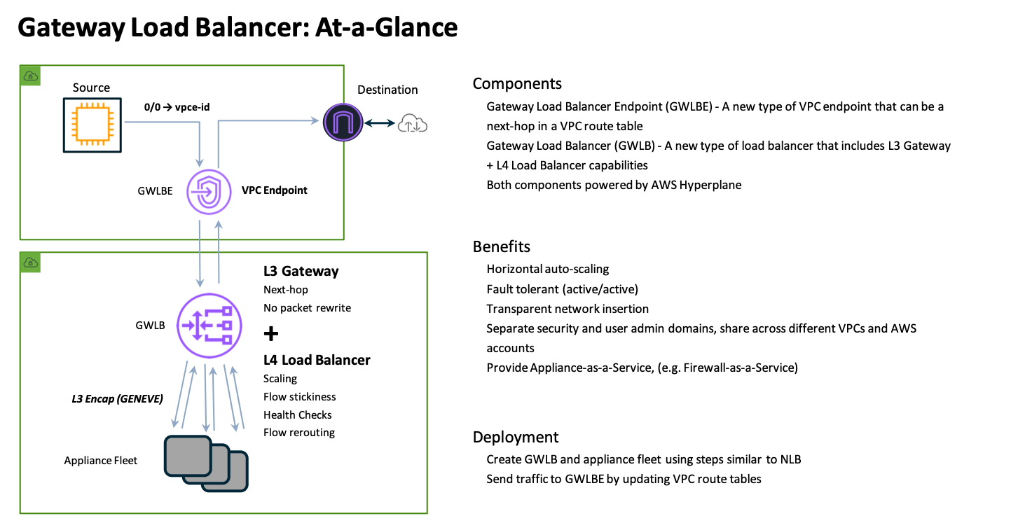
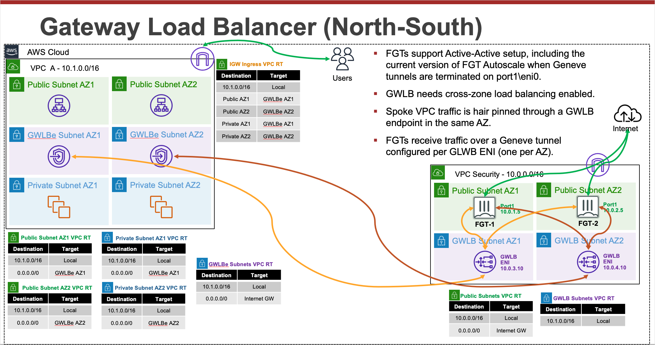
GWLB is a load balancer that accepts all IP traffic and forwards this to targets in a target group. GWLB supports being deployed into multiple availability zones. GWLB itself receives traffic with the use of GWLB endpoints (GWLBe). GWLBe are VPC endpoints that you deploy into your workload VPCs subnets. Then you can use VPC routing to send traffic to the GWLBe in the same availability zone.
With the introduction of VPC Ingress Routing back in 2019, you can apply VPC route tables to an Internet Gateway (IGW) or Virtual Private Gateway (VGW). This allows you to direct traffic destined to a local VPC subnet to a GWLBe in the same availability zone. This means you can inspect inbound traffic before it is sent to a public load balancer or instance.
Once the GWLBe receives the traffic, it uses PrivateLink to privately route the traffic to a GWLB node in the same availability zone. Since GWLB can be deployed across multiple availability zones, there is a GWLB node in each availability zone. For more details on this, reference AWS Documentation.
Each GWLB node uses an IP listener to receive the traffic and then forward traffic to the target group specified in the listner rule. GWLB nodes maintains stickiness of flows to a specific target group member using 5-tuple hash (for TCP/UDP flows) or 3-tuple hash (for non-TCP/UDP flows). This allows traffic for a specific flow to symmetrically be routed to the same FortiGate so layer 7 NGFW inspection, including SSL Man in the Middle (MitM), can be applied.
GWLB has a fixed idle timeout of 350 seconds for TCP flows and 120 seconds for non-TCP flows. Once the idle timeout is reached or a TCP connection is closed for a flow, it is removed from GWLB’s connection state table. To prevent this from happening, it is recommended to configure TCP keep-alive setting to less than 350 seconds on either client/server’s application/Operating System (OS). Reference AWS Documentation.
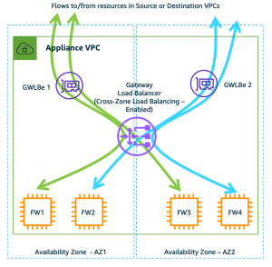
By default, each GWLB node deployed in an availability zone distributes traffic across the registered and healthy targets within the same availability only. If you enable cross-zone load balancing, each GWLB node distributes traffic across all registered and healthy targets in all enabled Availability Zones.
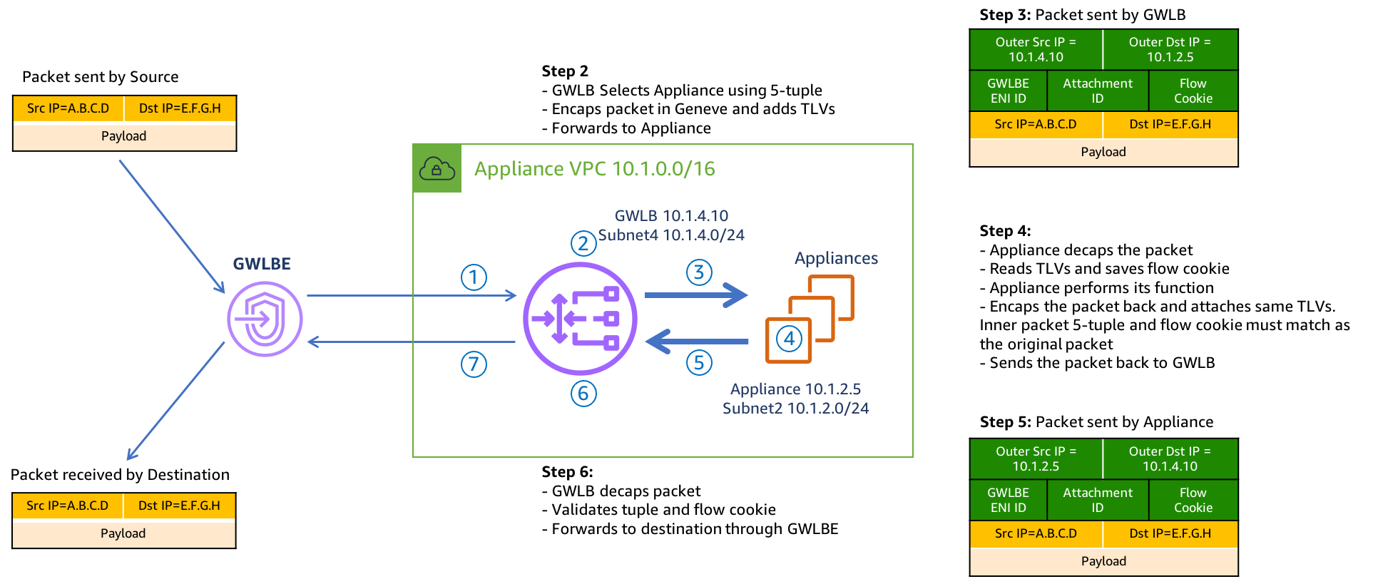
Once a GWLB node picks a target to send traffic to, it will encapsulate the data plane traffic in a GENEVE tunnel and forwards this to the target. When the FortiGate receives the GENEVE traffic, it will terminate the tunnel and inspect the original data plane traffic using NGFW policies and features. The GENEVE tunnel header uses TLVs that includes information such as the VPC endpoint id of the GWLBe that received the original traffic and the flow hash. For more details on this, reference AWS Documentation.
After NGFW inspection, the FortiGate can use simple policy and static routing to either route the traffic back to the same GWLB node using a GENEVE tunnel or send this out a local interface to access internet-based resources. With simple policy and routing changes you can change how routing is handled to support different use cases.
After the GWLB node receives the traffic back from the FortiGate, it sends the traffic back to the same GWLBe that originally received the traffic. Finally, the GWLBe in the workload VPC will send the traffic to the intrinsic router which uses the assigned VPC route table’s routes to send the traffic to the destination.
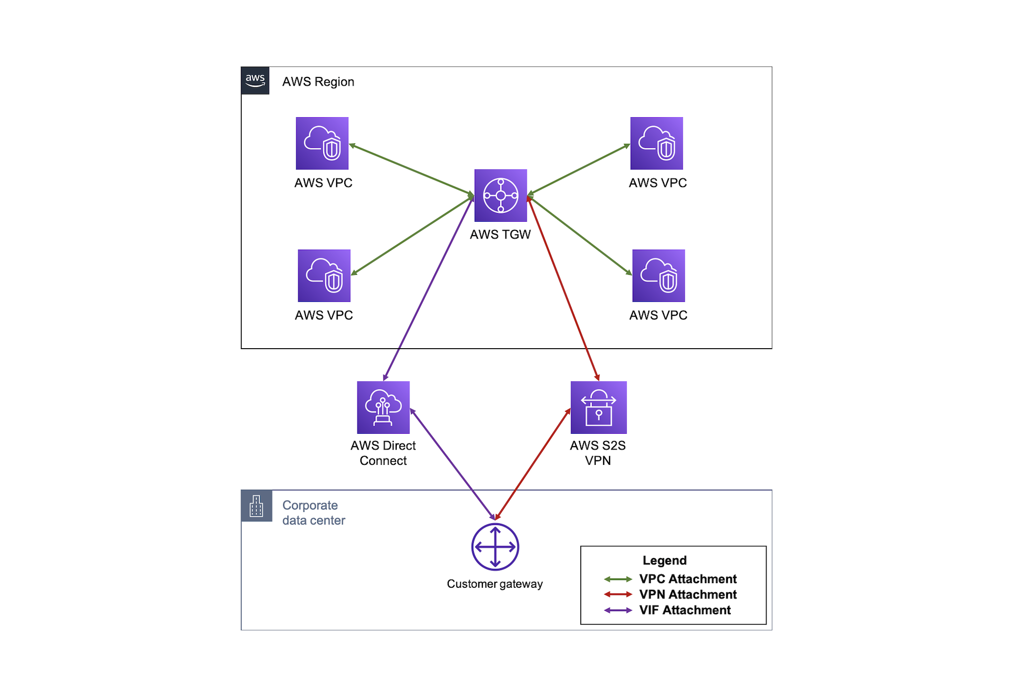
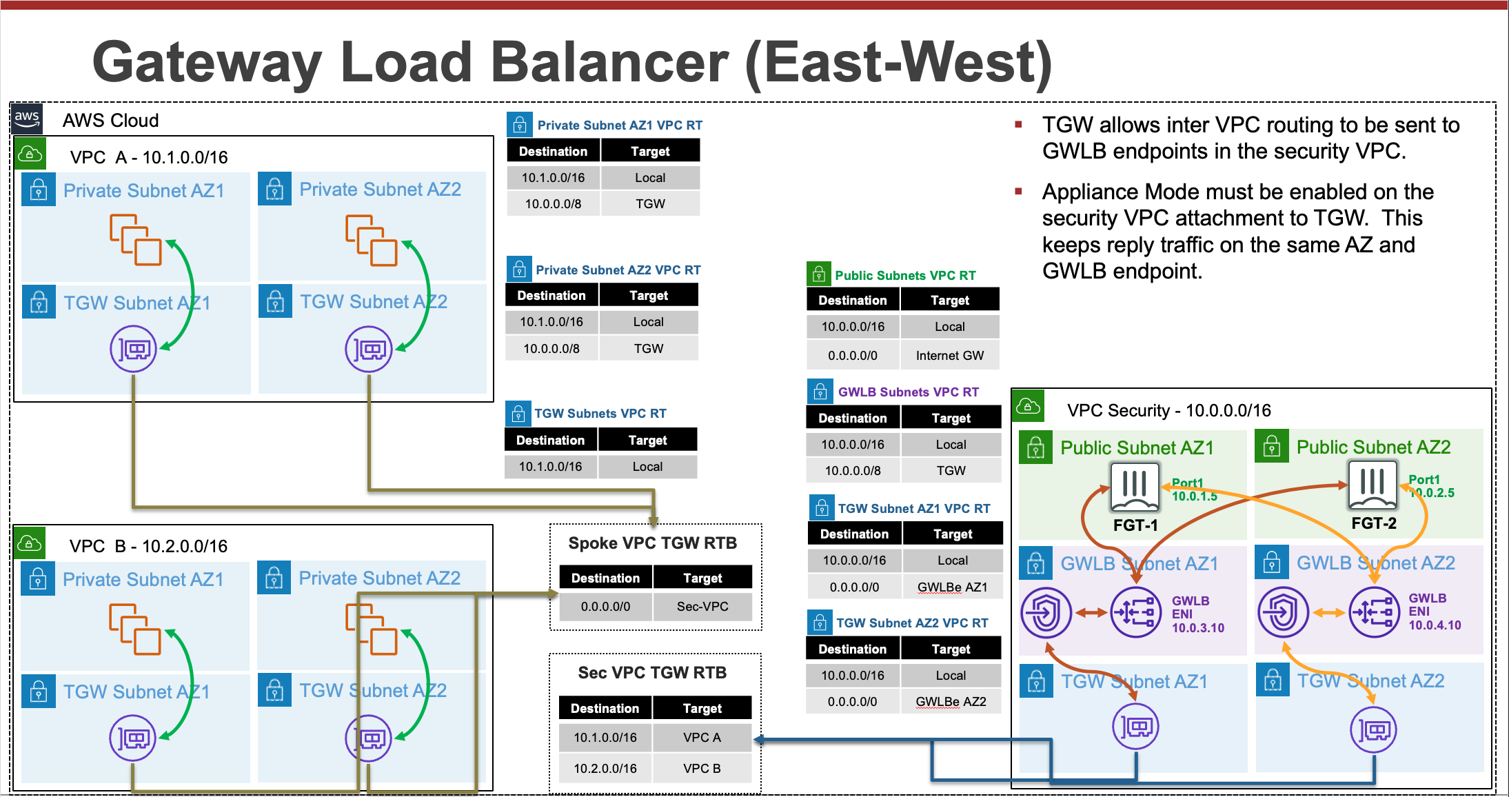
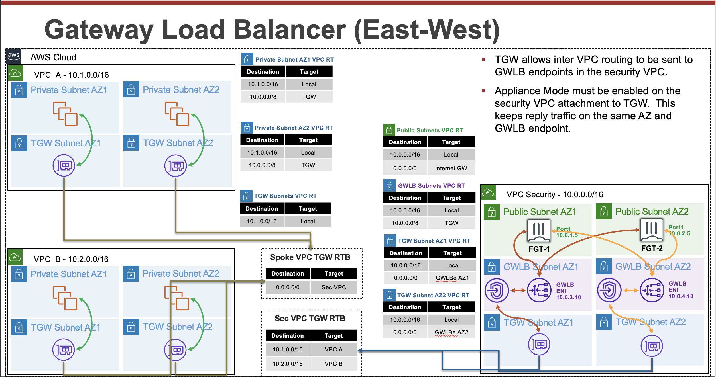
TGW is a highly scalable cloud router that connects your VPCs in the same region to each other, to on-premises networks, and even to the internet through one hub. With the use of multiple route tables for a single TGW, you can design hub and spoke routing for traffic inspection and enforcement of security policy across multiple VPCs. Notice the TGW RTBs below allow the FortiGates in the inspection VPC inspect east/west traffic between the spoke VPCs. As the name implies, Transit Gateway supports transitive routing. This means the inspection VPC can be used for east/west, centralized egress, and centralized ingress as well.
Expand each section to see the details.
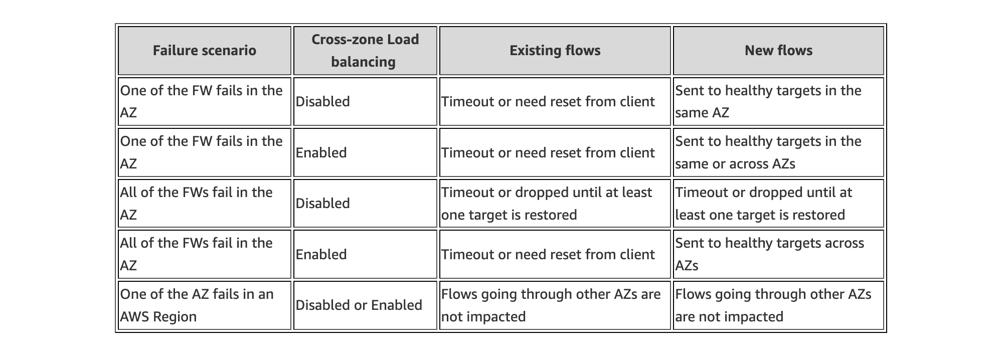
AWS Elastic Load Balancing services all have a form of health checking targets in a target group to provide resiliency. With GWLB an important point to note is how target failure behavior is handled when all targets in a single availability zone have failed.
By default, cross zone load balancing is disabled on GWLB. This means that if all targets in a single availability have failed (ie AZ1), the GWLB node in that same availability zone will not send traffic to healthy targets in different availability zone (ie AZ2). Instead, the GWLB node will fail open and continue to send any traffic it receives to the same unhealthy targets in the same availability zones.
To change this behavior, you can simply enable cross zone load balancing. This changes the behavior so that if all targets in a single availability have failed (ie AZ1), the GWLB node in that same availability zone will send traffic to healthy targets in different availability zones (ie AZ2, AZ3). In fact, with cross zone load balancing enabled, the GWLB nodes will be evenly distributing traffic to healthy FortiGates in all zones.
Thus we recommend that cross zone load balancing should be enabled for the best resiliency for your environment. For more details on this, reference AWS Documentation.
It is best practice to use Infrastructure as Code (IaC) templates to deploy FortiGates & GWLB in AWS as there are quite a bit of components that make up the entire solution. These can be used to deploy a new VPC. You can also integrate with a new or existing Transit Gateway as well.
Reference the CloudFormation and Terraform templates in the Github repos below and reference the quick start guides for how to use these for a deployment.
You will need administrator privileges to run these templates as they are creating IAM roles, policies, and other resources that are required for the solution and automating deployment.
fortigate-aws-gwlb-cloudformation
fortigate-aws-gwlb-terraform
This is picking up after a successful deployment of FGCP with CloudFormation. The same steps can be used, post deployment, to validate a successful setup and test failover.
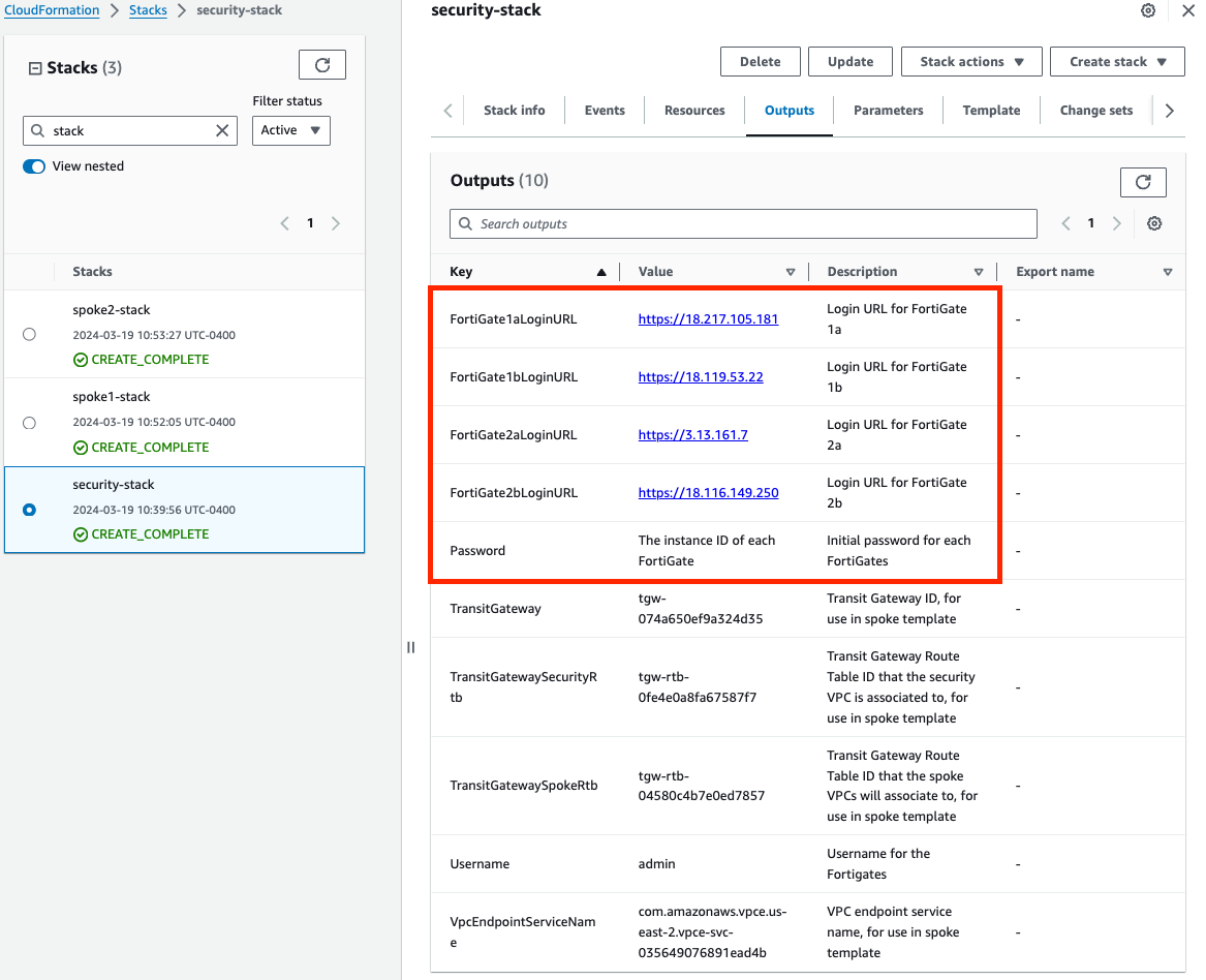
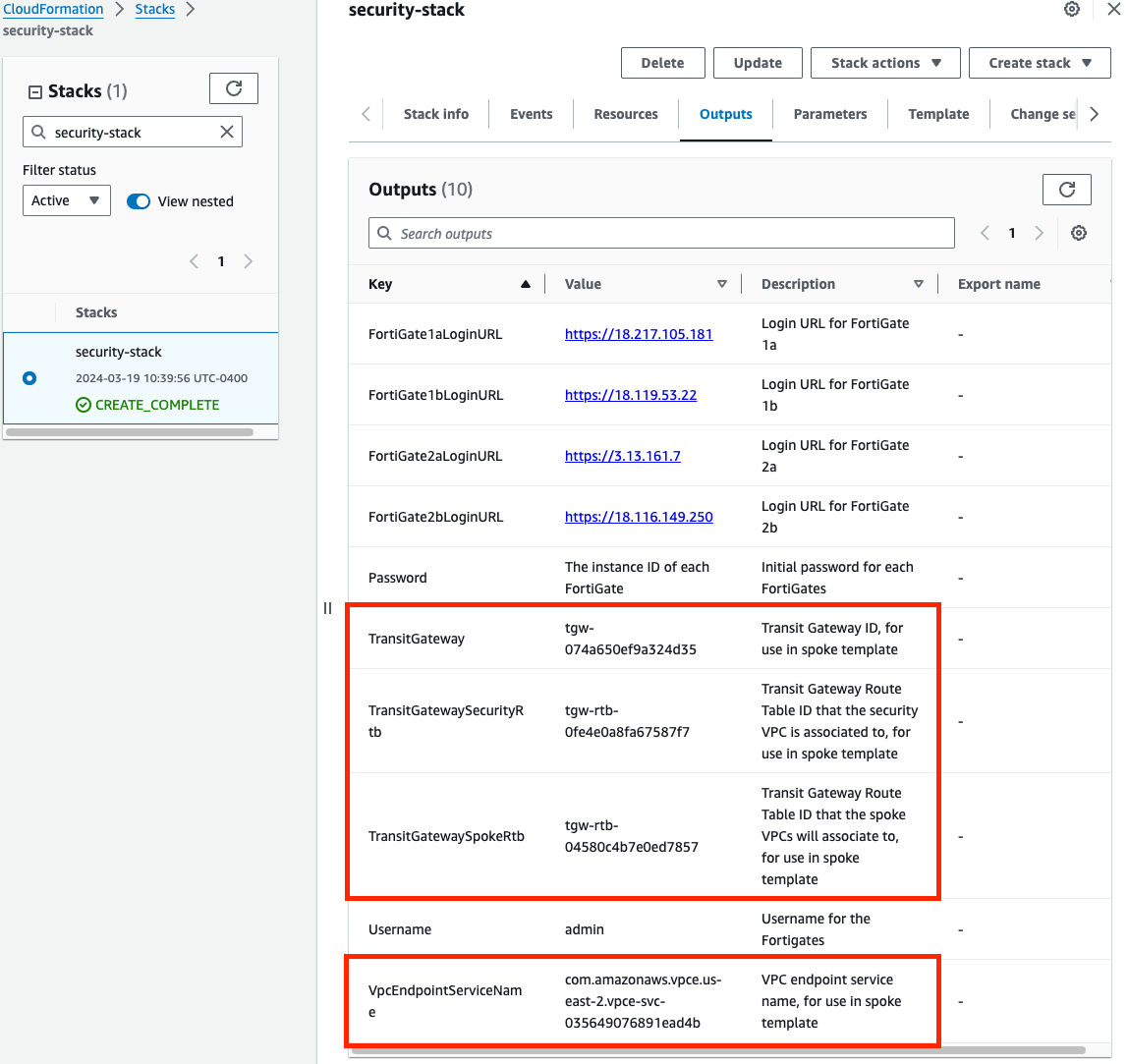
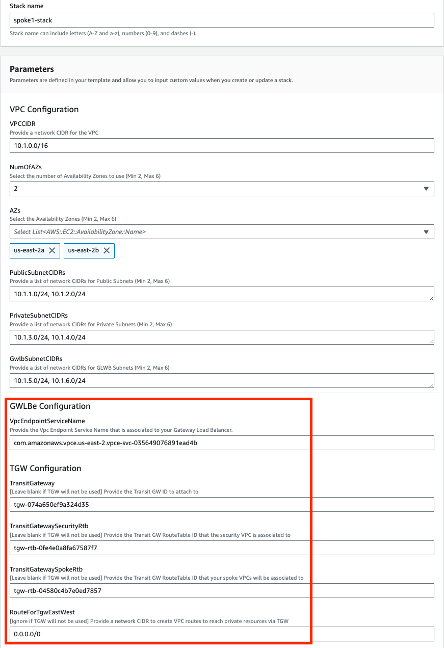
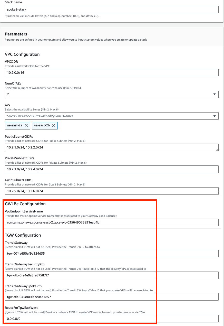
When using CloudFormation, your stack will have outputs you can use to login to the FortiGates via the cluster or dedicated EIPs. If you used Terraform, these outputs will be listed in your terminal session. If you chose to deploy a new TGW as part of the deployment you will see the IDs of your Transit Gateway and TGW Route Tables. These can be used as inputs for the ‘SpokeVPC_TGW_MultiAZ.template.json’ template.
Apply complete! Resources: 85 added, 0 changed, 0 destroyed.

Outputs:

fgt_login_info = <<EOT
# fgt username: admin
# fgt initial password: instance-id of the fgt
# fgt_ids_a : ["i-053888445f2e677ef","i-09c5e7a6bf403cd77"]
# fgt_ips_a : ["34.235.8.29","52.70.176.130"]
# fgt_ids_b : ["i-094aae24d8f1665b0","i-0575b16f6aeeb0e15"]
# fgt_ips_b : ["3.210.241.134","44.196.135.34"]

EOT
gwlb_info = <<EOT
# gwlb arn_suffix: gwy/poc-sec-gwlb/09856ffbfe1862f3
# gwlb service_name : com.amazonaws.vpce.us-east-1.vpce-svc-0db0f1b8e4b8445f1
# gwlb service_type : GatewayLoadBalancer
# gwlb ips : ["10.0.13.83","10.0.14.93"]

EOT
tgw_info = <<EOT
# tgw id: tgw-09eb29c4aa20fe1ce
# tgw spoke route table id: tgw-rtb-0b080f43f34fd129d
# tgw security route table id: tgw-rtb-0c09fcc9ce8d3e917

EOTWe deployed some workload instances in both spoke VPCs to generate traffic flow through the security stack.
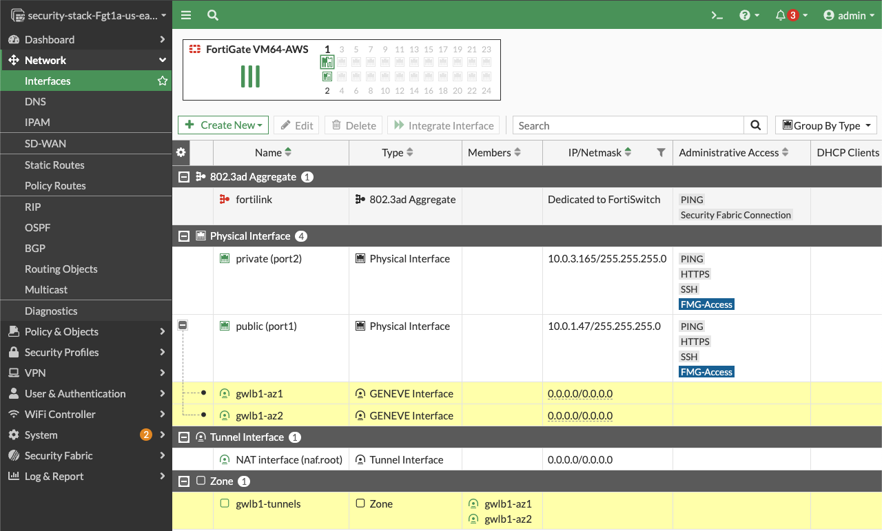
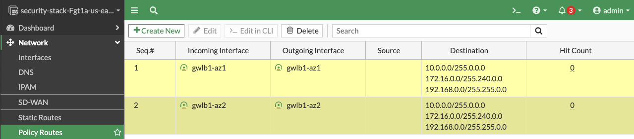
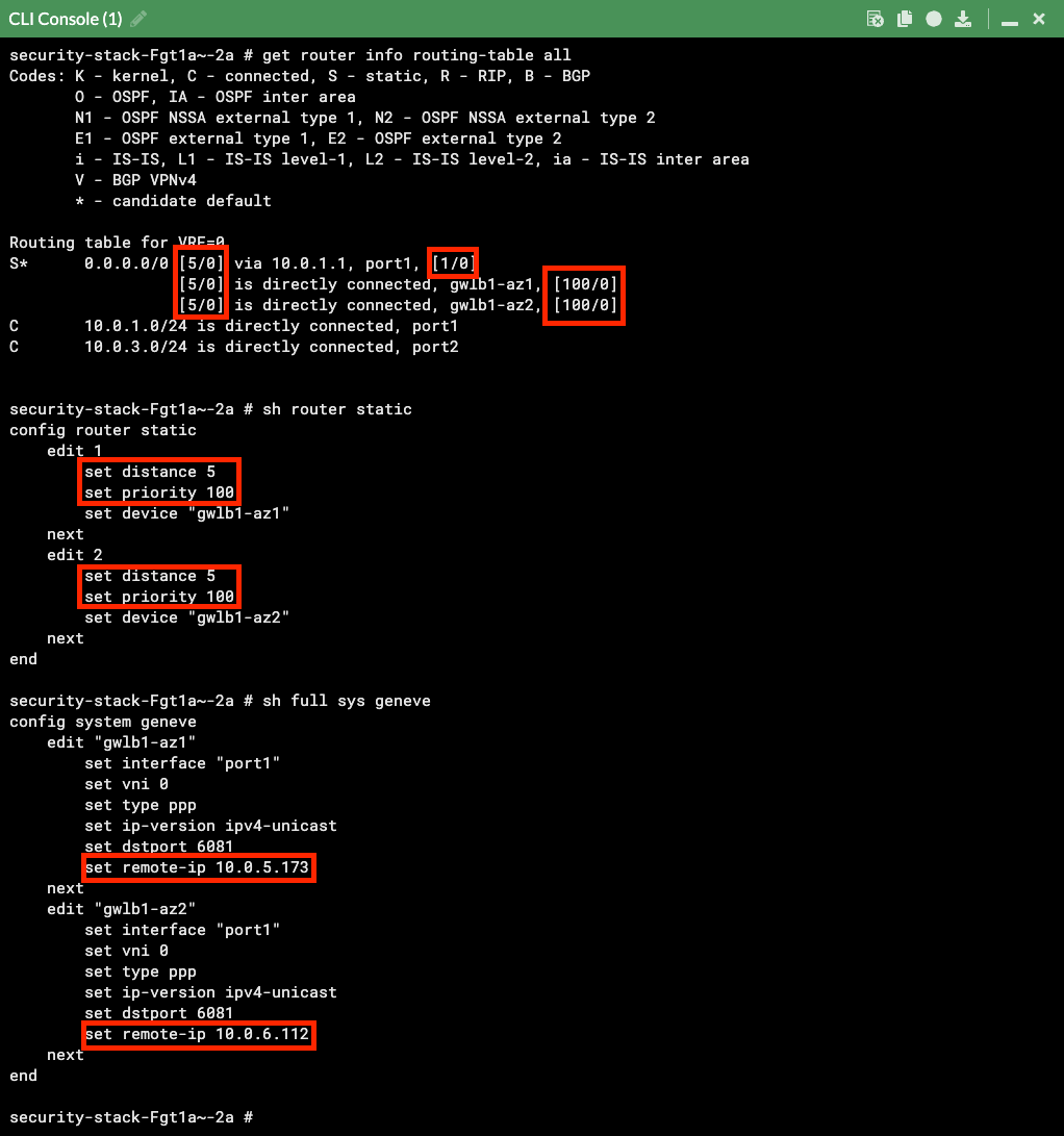
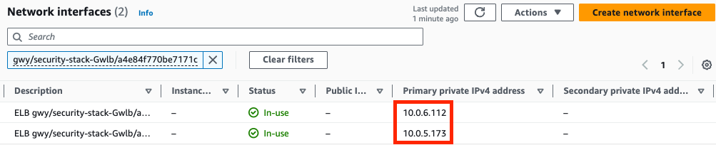
On the FortiGate GUI navigate to Network > Interfaces, Network > Policy Routes, and run the CLI commands below to see the bootstrapped networking config. Notice the GENEVE tunnels are between the FGT port1 interface IP and the private IP of the GWLB node ENI IP. Also notice the priority settings in the static routes and policy routes which allow using the FGTs as NAT GWs for internet bound traffic but to hairpin east/west traffic.
You can check that the license provided and base config passed is applied successfully with the commands below.
diag debug cloudinit show
get system status
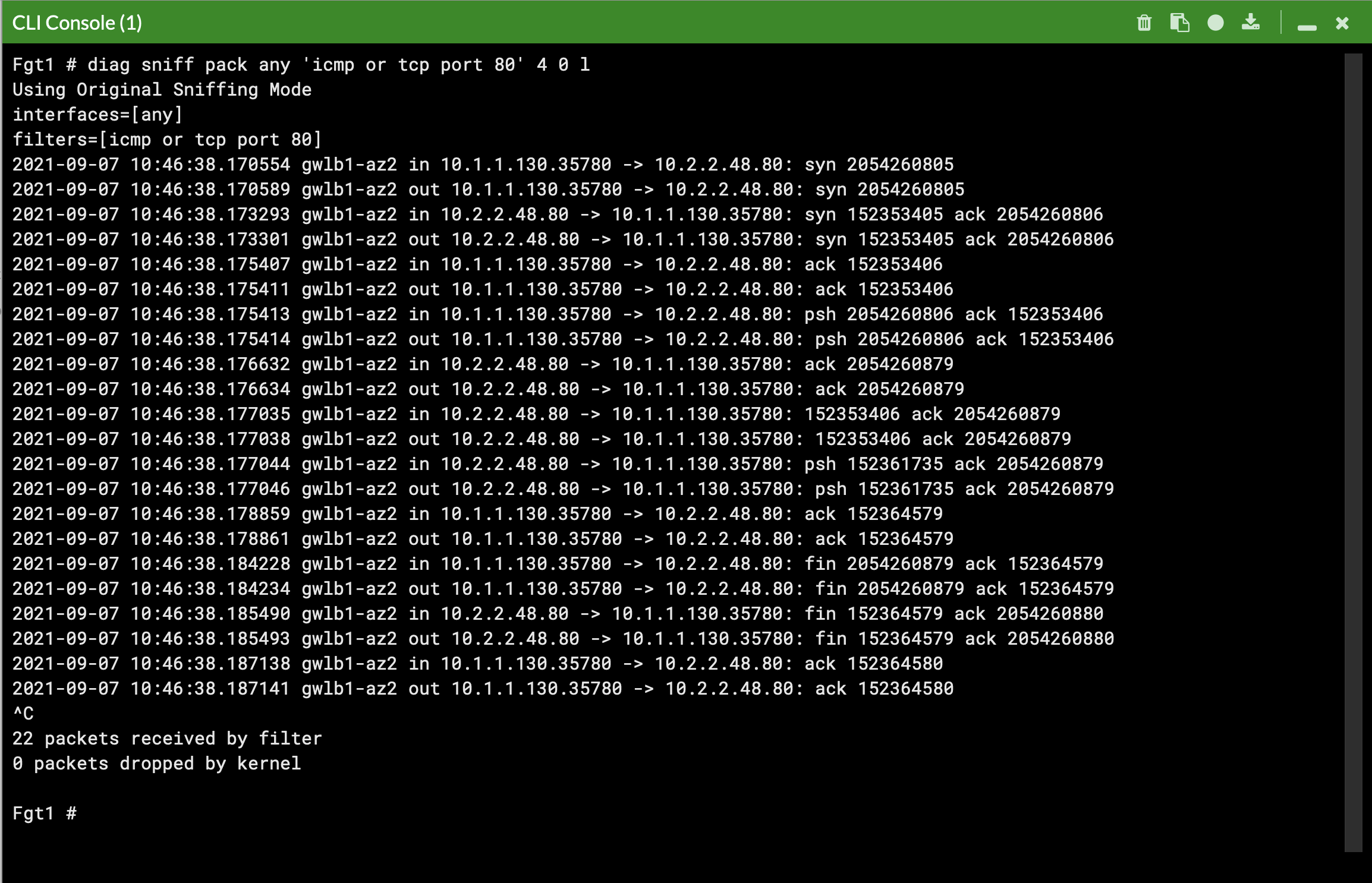
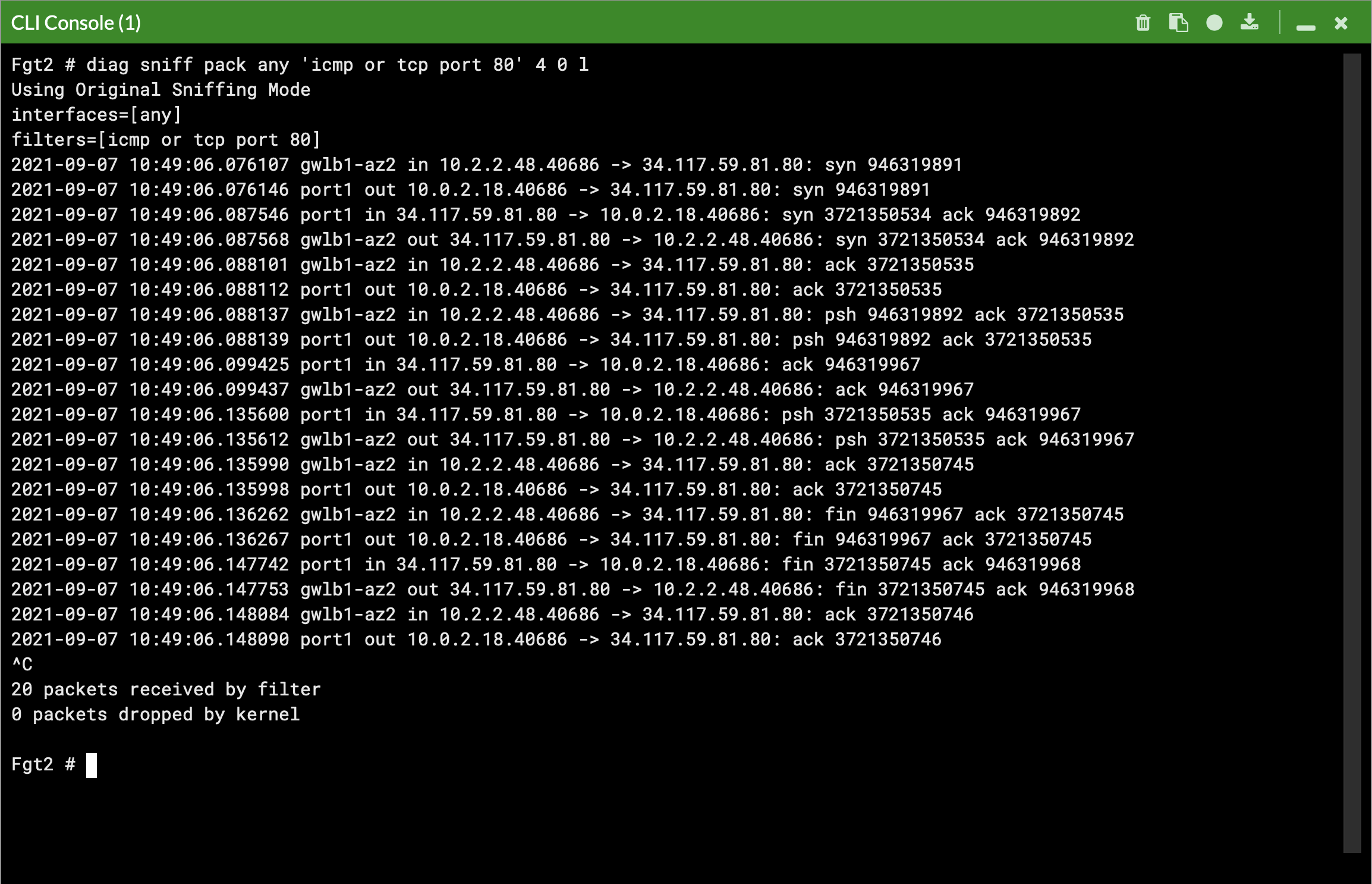
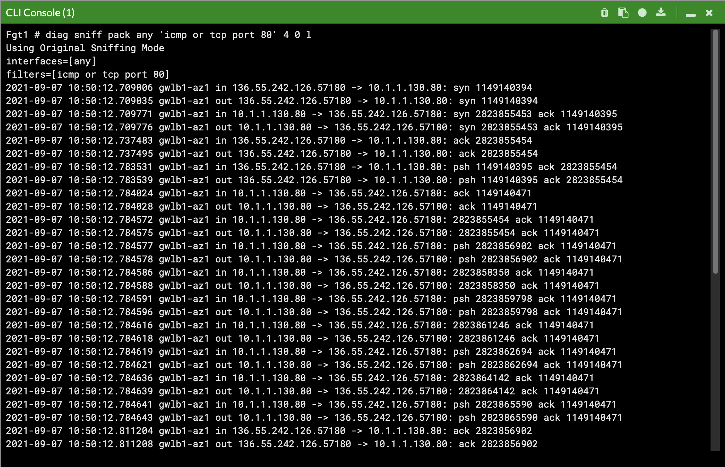
diag debug vm-print-licenseAfter accessing one of the jump box instances, we can use a sniffer command on one or all FGTs to see traffic flow over the GENEVE tunnels to different destinations. Since the GWLB will hash traffic based on source/dest IPs, Ports, and Protocol, either run the sniffer command on all FGTs or temporarily shutdown all FGTs but one to easily verify traffic flow.
Notice that the FGTs are acting as a NAT GW for internet bound traffic and Source NATing the traffic and routing it out port1, while east/west is hair pinned back to the correct geneve tunnel.
This concludes the post deployment example.
While there are many ways to organize your infrastructure there are two main ways to design your networking when using GWLB, centralized and distributed. From the perspective of networking, routing, and GWLBe endpoint placement
Expand each section to see the details.
Decentralized designs do not require any routing between the protected VPC and another VPC through TGW. These designs allow simple service insertion with minimal routing changes to the VPC route tables. The yellow numbers show the initial packet flow for a session and how it is routed (using ingress and VPC routes) to the GWLBe endpoint which then sends traffic to the FortiGate CNF stack. The blue numbers show the returned traffic after inspection by the FortiGate CNF stack.


Centralized designs require the use of TGW to provide a simple hub and spoke architecture to inspect traffic. These can simplify east-west, egress, and ingress traffic inspection needs while removing the need for IGWs and NAT Gateways to be deployed in each protected VPC for egress inspection. You can still mix a decentralized architecture to inspect ingress and even egress traffic while leveraging the centralized design for all east-west inspection. The yellow numbers show the initial packet flow for a session and how it is routed (using ingress, VPC routes, and TGW routes) to the GWLBe which then sends traffic to the FortiGate CNF stack. The blue numbers (east-west) and purple numbers (egress) show the returned traffic after inspection by the FortiGate CNF stack. In a single region, you can have one deployment of FGTs & GWLB support both distributed and centralized designs. This all comes down to implementing the appropriate routing at the VPC & TGW route tables and FortiGate routes.
Centralized


Supporting Both Models

Expand each section to see the details.
GWLB supports two different models of firewall deployments, one-arm and two-arm where a firewall appliance can also perform NAT.
In the one-arm model, the FortiGates will inspect traffic and forward this back to GWLB where internet bound traffic is has NAT applied by a NAT GW. Typically, the NAT GW will be in a workload VPC in a distributed design. Distributed designs have GWLBe endpoints in each workload VPC that requires to have an attached Internet Gateway (IGW) and public load balancer or NAT GW.

We can use static and policy routes like below to support this setup. In a 2 AZ deployment there are two static routes using priority setting to bypass the reverse path filtering check when receiving data plane traffic over the GENEVE tunnels. The static routes are default routes to simplify the config, but you could also specify a route for each spoke VPC for each GENEVE tunnel. Also, there are two policy routes to hairpin traffic received over each GENEVE tunnel, back to the same one.
config router static
edit 1
set distance 5
set priority 100
set device gwlb1-az1
next
edit 2
set distance 5
set priority 100
set device gwlb1-az2
next
end

config router policy
edit 1
set input-device gwlb1-az1
set output-device gwlb1-az1
next
edit 2
set input-device gwlb1-az2
set output-device gwlb1-az2
nextIn the two-arm model, the FortiGates will inspect traffic and forward & SNAT traffic out port1 (public interface) to act as a NAT GW. This removes the need for deploying NAT GWs in each AZ of each workload VPC. This is a centralized design where the data plane traffic used TGW to reach the GWLBe endpoints in the inspection/security VPC and be inspected by the FortiGates. We can use static and policy routes like below to support this setup. In a 2 AZ deployment there are two static routes using priority setting to bypass the reverse path filtering check when receiving data plane traffic over the GENEVE tunnels. The static routes are default routes to simplify the config, but you could also specify a route for each spoke VPC for each GENEVE tunnel. Also, there are two policy routes to hairpin traffic received over each GENEVE tunnel, back to the same one. These policy routes will only hairpin traffic destined RFC1918 addresses and will route internet bound traffic out port1.
Two-Arm Model (Centralized)

config router static
edit 1
set distance 5
set priority 100
set device gwlb1-az1
next
edit 2
set distance 5
set priority 100
set device gwlb1-az2
next
end

config router policy
edit 1
set input-device gwlb1-az1
set dst "10.0.0.0/255.0.0.0" "172.16.0.0/255.240.0.0" "192.168.0.0/255.255.0.0"
set output-device gwlb1-az1
next
edit 2
set input-device gwlb1-az2
set dst "10.0.0.0/255.0.0.0" "172.16.0.0/255.240.0.0" "192.168.0.0/255.255.0.0"
set output-device gwlb1-az2
next
When inspecting ingress traffic, it is common to need to control traffic for specific public resources such as Public ALBs & NLBs. While you can create a broad firewall policy that controls traffic destined to the protected public subnets, giving every public resource the same level of control, more granularity is needed.
While we can use the load balancer DNS A record to resolve the public IPs, this does not give us the private IPs. When inspecting ingress traffic with GWLB, we need to match NGFW policy based on the private IPs.

To accomplish this, we can use the SDN connector in advanced mode to allow us to search for resources based on attributes such as owner ID, resource descriptions, and tags. For ALBs/NLBs we can use the description of the network interfaces to dynamically find the public or private IPs.
Here is an example of searching for the network interfaces of the load balancer by description. We are searching using the tail end of the load balancer ARN shown in the picture above, in the bottom left of the load balancer details pane.

You can enable this advanced or alternate resource mode for an SDN connector with the command set alt-resource-ip enable. Here is an example SDN config:
config system sdn-connector
edit aws-instance-role
set status enable
set type aws
set use-metadata-iam enable
set alt-resource-ip enable
next
end
Once enabled, you create a dynamic address object using the description of the load balancers. This will be polled and resolve to the current private IPs of any matching network interfaces. Now we can easily create per application NGFW policies and control traffic to the dynamic IPs of the load balancers.


Yes. This can be done but would require you to use an IP based target group instead of an Instance based target group. This would not work for the official FortiGate Auto Scale solution so this would be limited to a manual scale deployment.
No. Traffic must come through a GWLBe endpoint so that GWLB knows where to send the reply traffic for each flow. For example, this means that traffic generated by the FGT itself will need to go out port1 (to public resources) or port2 (to private resources). To reach private resources, create static routes on the FGTs with the AWS VPC router for the connected private subnet to reach private resources (within the same VPC or via TGW). The VPC router is the first host IP of each AWS subnet, (ie 10.1.0.1 host IP for 10.1.0.0/24 subnet).