Public Cloud 202: Azure Networking with vWAN Internet Inbound
In this course you will learn how to deploy a FortiGate network virtual appliance (NVA) to an existing Azure Virtual WAN (vWAN) to meet the connectivity and security requirements of Company ABC as they move server workloads, from existing managed hubs and VNETs, to the managed vWAN service.
This course will start with understanding key resources and terminology used in Azure when deploying vWAN, hubs, VNETs, routing services, and FortiGate NVAs.
The course continues with the deployment of active/active FortiGate NVAs to secure the vWAN and configuring the the FortiGate NVAs to route and manage network traffic between Company ABC’s hosted services located in VNETs.
Course Goals
Learn key Azure vWAN resources and terms related to this course
Deploy a pair of FortiGate Network Virtual Appliances (NVAs) to an existing Azure vWAN hub and configure FGSP
Configure dynamic routing with BGP and enable Routing Intent
Peer Azure Virtual Networks (VNETs) to the vWAN Hub
Deploy a second vWAN hub, create and peer a VNET, and manage network traffic between the vWAN hubs
Continue to Chapter 1: Reference Diagrams
Subsections of Public Cloud 202: Azure Networking with vWAN Internet Inbound
Chapter 1: Reference Diagrams
Course Reference Diagrams
The following reference diagrams will be used throughout this course.
The following two architectures will be deployed:
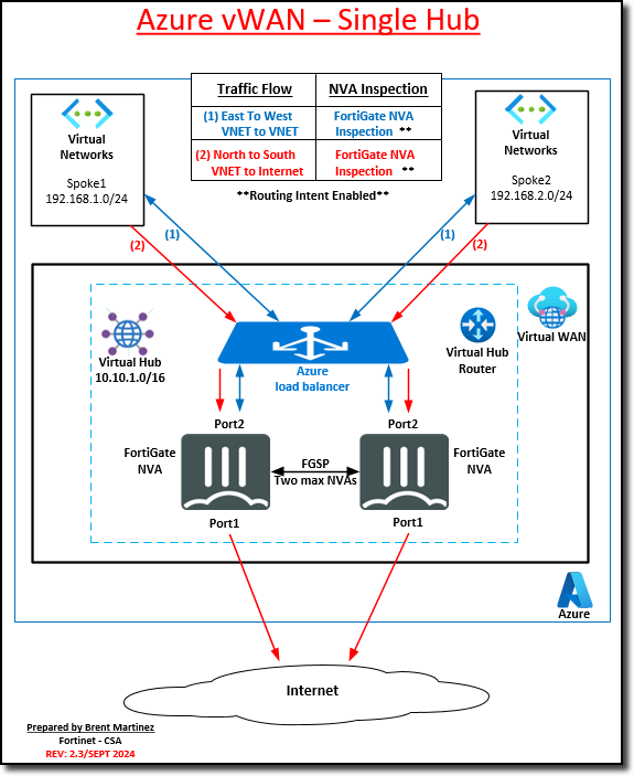
Active/Active FortiGate NVAs in a single existing vWAN hub
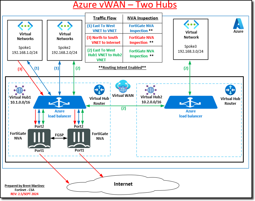
Expand the architecture with deployment of a second vWAN hub, a VNET, and routing. Network traffic between the hubs will be managed through the FortiGate NVAs
Continue to Chapter 2 - Azure Virtual WAN Concepts
Chapter 2: Azure Virtual WAN Concepts
This chapter covers Azure vWAN managed service and the key components that make up a virtual WAN. These terms and services will be used extensively in this course.
Overview
Task 1: Azure Virtual WAN (vWAN)
Task 2: Azure vWAN resources
Task 3: FortiGate NVA Support for vWAN
Continue to Chapter 2 - Task 1: Azure Virtual WAN
Subsections of Chapter 2: Azure Virtual WAN Concepts
Task 1: Azure Virtual WAN
Azure Virtual WAN
Azure Virtual WAN is a networking service that brings many networking, security, and routing functionalities together to provide a single operational interface. Some of the main features include:
Branch connectivity (via connectivity automation from Virtual WAN Partner devices such as SD-WAN or VPN CPE).
Site-to-site VPN connectivity.
Remote user VPN connectivity (point-to-site).
Private connectivity (ExpressRoute).
Intra-cloud connectivity (transitive connectivity for virtual networks).
VPN ExpressRoute inter-connectivity.
Routing, Azure Firewall, and encryption for private connectivity.
All of these use cases are not required to start using Virtual WAN. Get started with just one use case and adjust as the network needs evolve.
The Virtual WAN follows a hub and spoke architecture with scale and performance built in for branches (VPN/SD-WAN devices), users (Azure VPN/OpenVPN/IKEv2 clients), ExpressRoute circuits, and virtual networks. Enabling a global transit network architecture, where the cloud hosted network ‘hub’ provides transitive connectivity between endpoints that can be distributed across different types of ‘spokes’.
Virtual WAN offers the following advantages:
Integrated connectivity solutions in hub and spoke: Automate site-to-site configuration and connectivity between on-premises sites and an Azure hub.
Automated spoke setup and configuration: Connect your virtual networks and workloads to the Azure hub seamlessly.
Intuitive troubleshooting: You can see the end-to-end flow within Azure, and then use this information to take required actions.
In this course, the vWAN has already been deployed.
Continue to Chapter 2 - Task 2: Azure vWAN resources
Task 2: Azure vWAN Resources
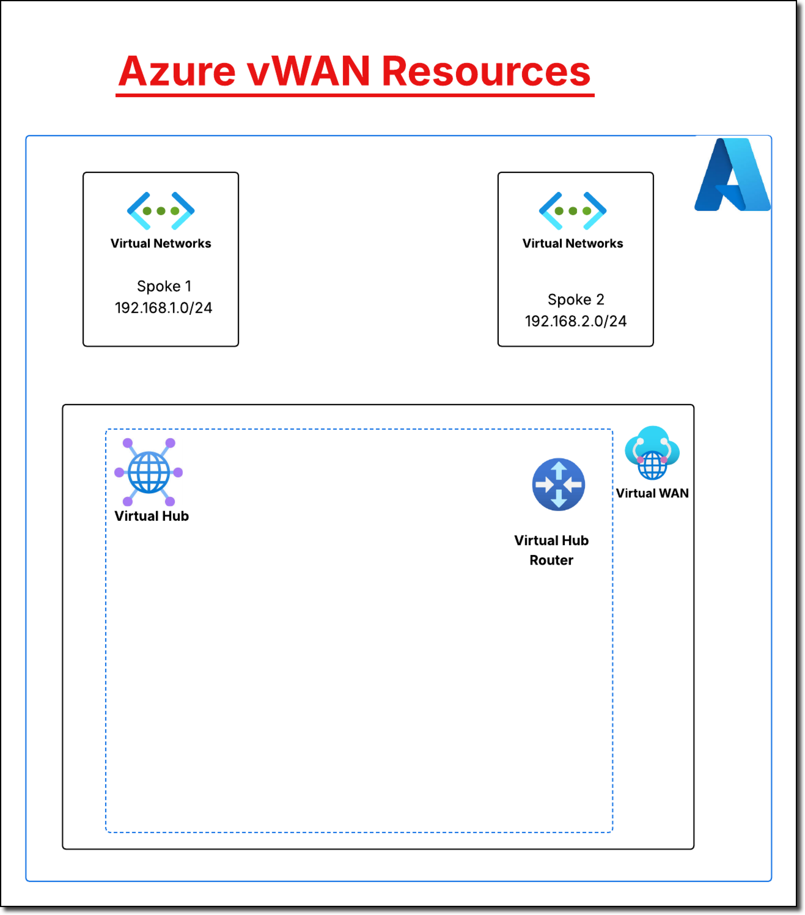
Azure vWAN Resources
To configure an end-to-end virtual WAN, create the following resources:
Virtual WAN: The virtual WAN resource represents a virtual overlay of your Azure network and is a collection of multiple resources. Containing links to all virtual hubs within the virtual WAN. Virtual WANs are isolated from each other and cannot contain a common hub. Virtual hubs in different virtual WANs do not communicate with each other.
Hub: A virtual hub is a Microsoft-managed virtual network. The hub contains various service endpoints to enable connectivity. From on-premises network (vpnsite), connections can be made to a hub VPN gateway, connect ExpressRoute circuits to a virtual hub, or even connect mobile users to a point-to-site gateway in the virtual hub. The hub is the core of the network in a region. Multiple virtual hubs can be created in the same region.
A hub gateway is not the same as a virtual network gateway used for ExpressRoute and VPN Gateway. For example, when using Virtual WAN, site-to-site connections are not made from on-premises sites directly to an Azure virtual network (VNET). Instead a site-to-site connection is made to the virtual hub. The traffic always goes through the hub gateway. This means that VNETs do not need their own virtual network gateway. Virtual WAN lets VNETs take advantage of scaling easily through the virtual hub and the virtual hub gateway.
Hub virtual network connection: The hub virtual network connection resource is used to connect the hub seamlessly to virtual networks. One virtual network can be connected to only one virtual hub.
Hub-to-hub connection: Hubs are all connected to each other in a virtual WAN. This implies that a branch, user, or VNET connected to a local hub can communicate with another branch or VNET using the full mesh architecture of the connected hubs. VNETs can also be connected within a hub transiting through the virtual hub, as well as VNETs across hubs, using the hub-to-hub connected framework.
Hub route table: virtual hub routes are applied to the virtual hub route table. Multiple routes can be added to the virtual hub route table.
These resources are used to manage network traffic and route to the FortiGate NVAs.
Continue to Chapter 2 - Task 3: FortiGate NVA Support for vWAN
Task 3: FortiGate NVA Support for vWAN
Microsoft Azure supports virtual WAN (vWAN) and partners with third-party solution providers, such as Fortinet, to deploy network virtual appliances (NVAs) to a vWAN hub.
FortiGate NVA
By combining stateful inspection with a comprehensive suite of powerful security features, FortiGate next generation firewall technology delivers complete content and network protection. This solution is available for deployment in the Microsoft Azure vWAN managed service.
In addition to advanced features such as an extreme threat database, vulnerability management, and flow-based inspection, features including application control, firewall, antivirus, IPS, web filter, and VPN work in concert to identify and mitigate the latest complex security threats.
FortiGate NVAs are deployed in an active/active high availability (HA) configuration with FortiGate-native FGSP synchronization between the NVAs.
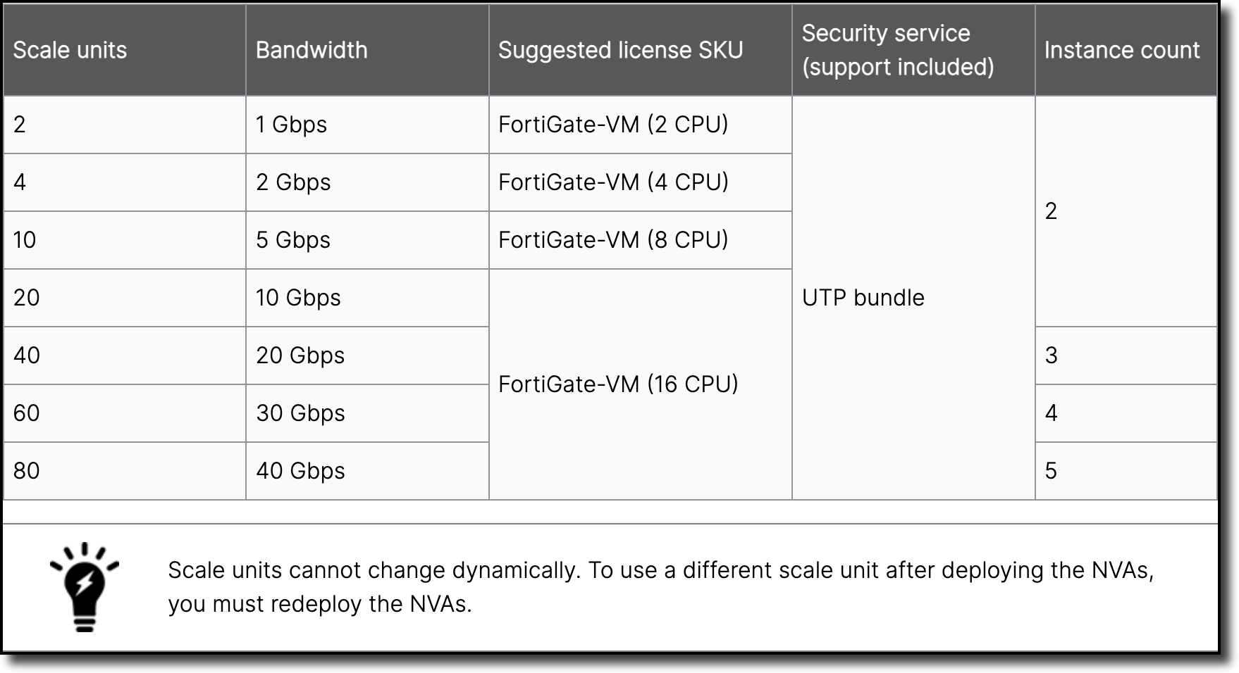
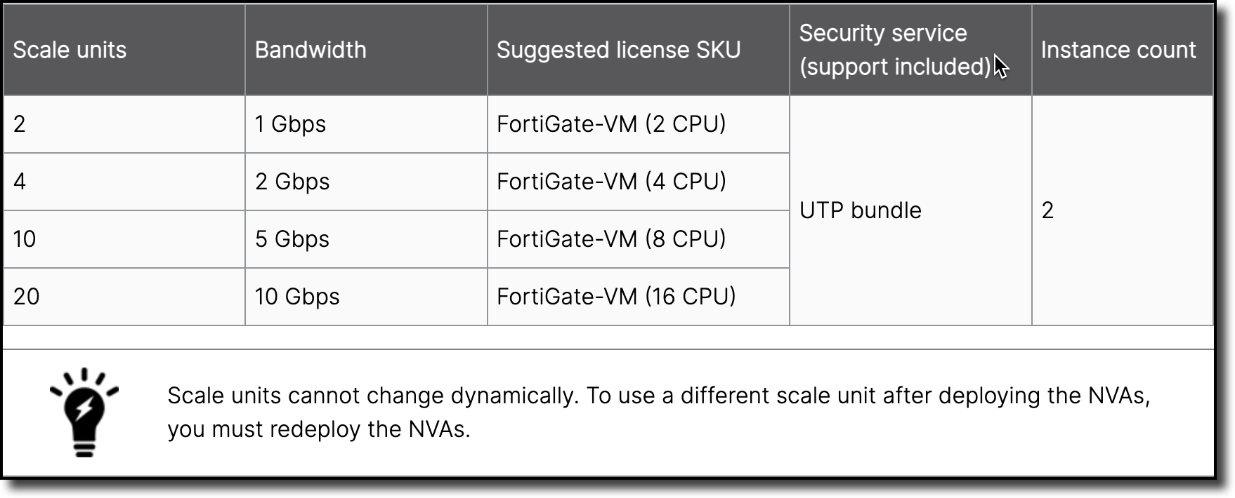
Order Types
Choose one of the following scale unit values when deploying FortiGate NVAs. Higher scale units are available for increased bandwidth requirements. A specific FortiGate virtual machine license is recommended for each scale unit value.
NGFW Deployment
SD-WAN NGFW Deployment
Tip
Azure has released new az cli commands that support changing the scale unit of a NVA with out the need to redeploy the environment. See NVA Management
Deployment Requirements
Deployment requires the following:
The number of required FortiGate licenses depends on the selected scale unit. Bring-Your-Own-License (BYOL), FortiFlex, and Pay-As-You-Go (PAYG) are all supported. the desired licensing method can be chosen during deployment.
One fully licensed FortiManager instance (BYOL or Flex) is recommended, but not required.
Continue to Chapter 3 - Getting Started
Chapter 3: Getting Started
In this chapter, review the credentials and login to the Azure portal with the assign credentials.
Overview
Lab Credentials
Azure Portal - Lab Access
Continue to Chapter 3 - Task 1: User Credentials
Subsections of Chapter 3: Getting Started
Task 1: User Credentials
These are the credentials that are used throughout the session.
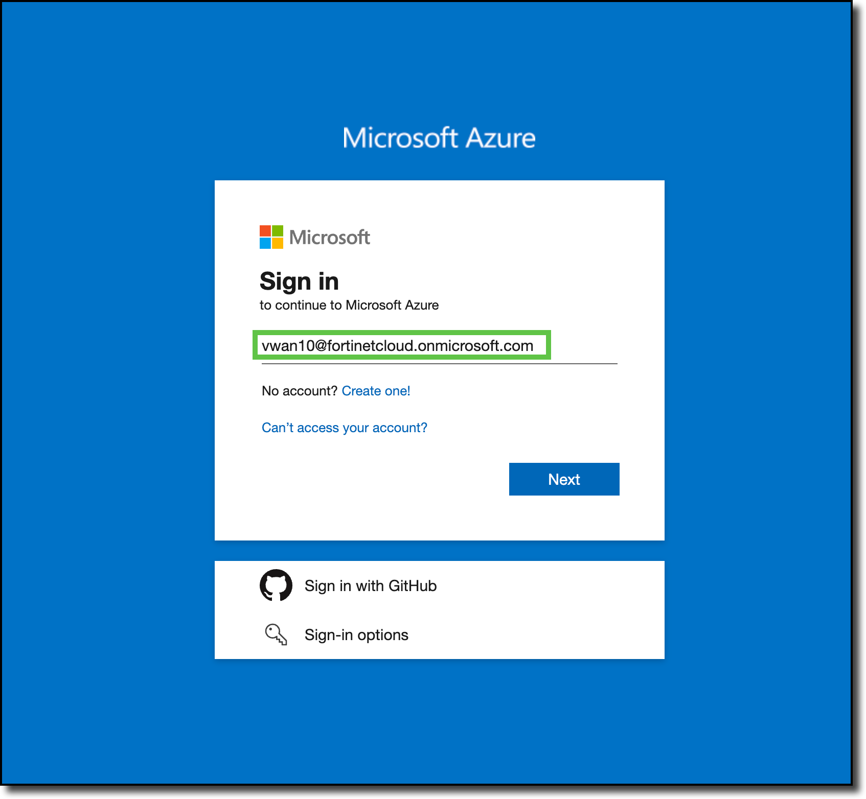
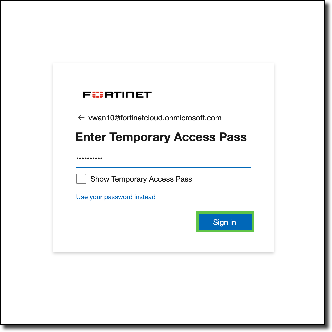
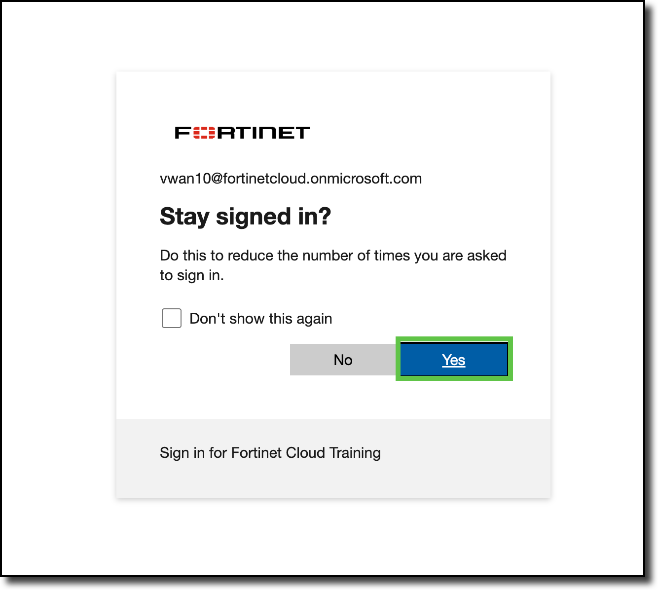
The work for this session takes place in Azure and on FortiGates deployed into the Azure Virtual WAN Hub. The first step is to logon to the Azure Portal.
Login to Azure Portal and Review Existing Resources
Click “Cancel” on the “Welcome to Microsoft Azure” page (if displayed)
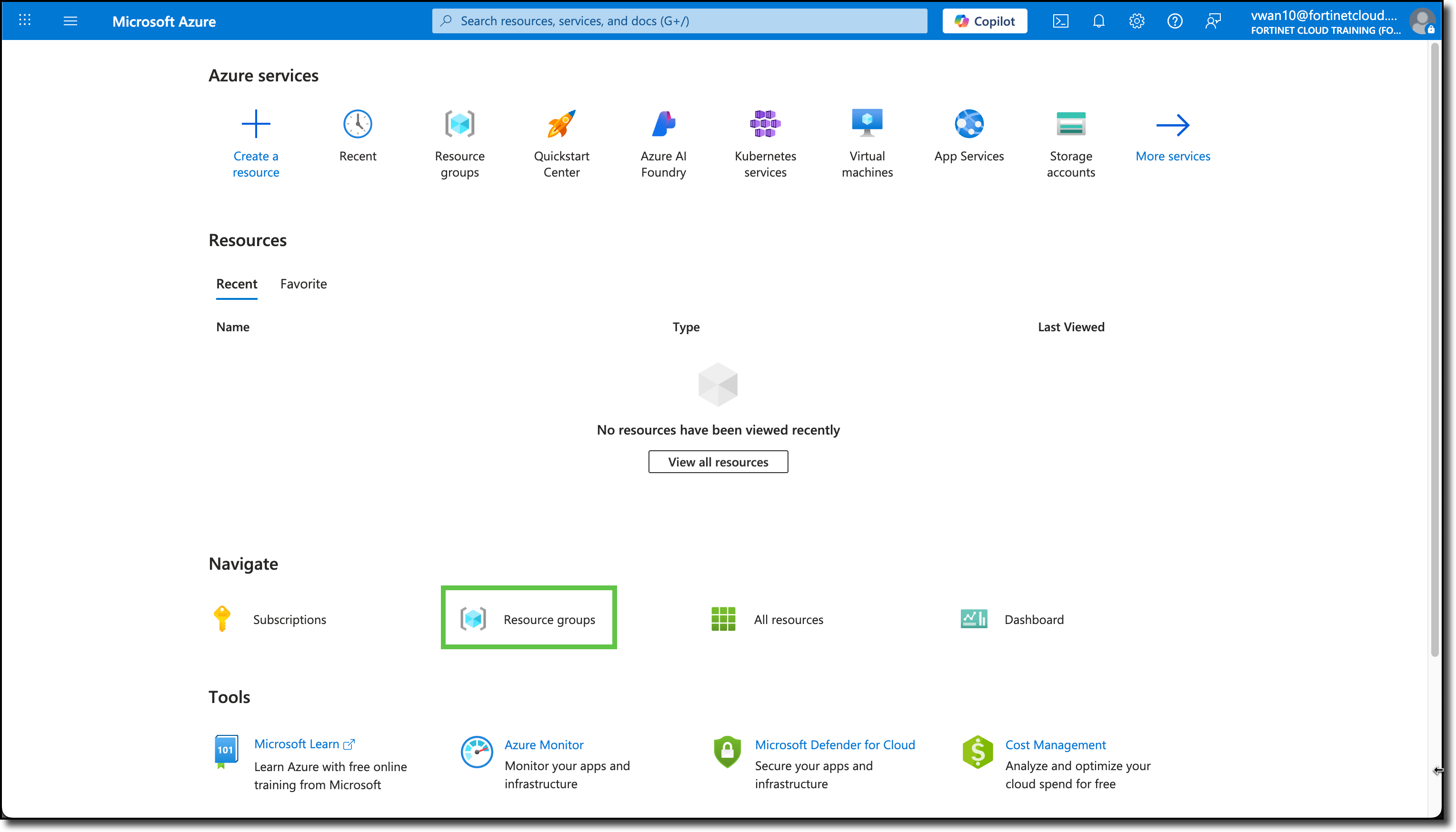
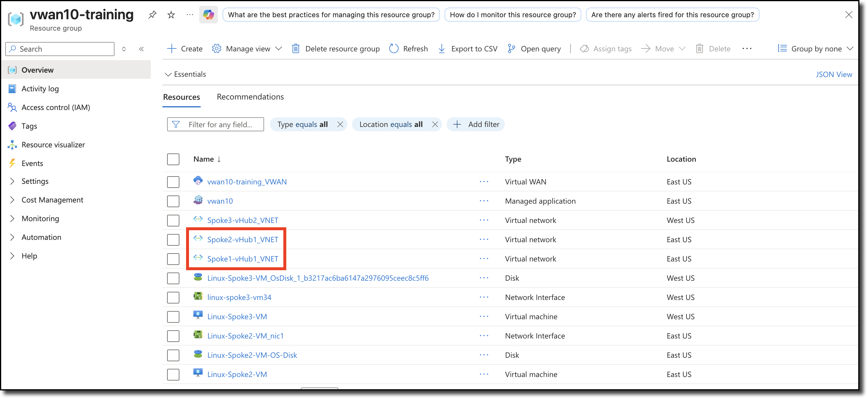
Click “Resource groups”
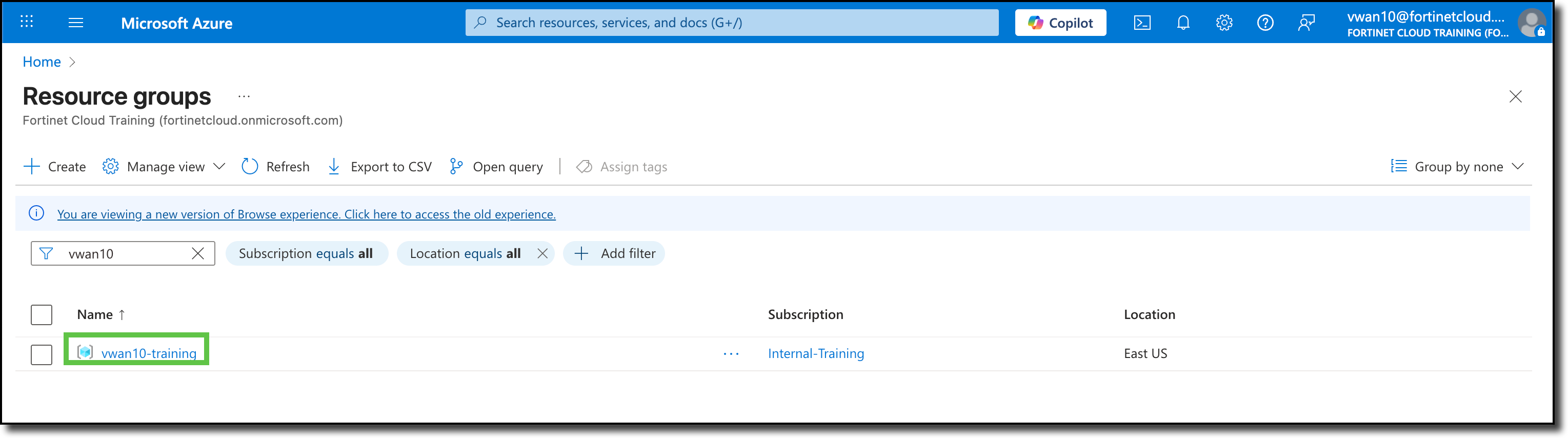
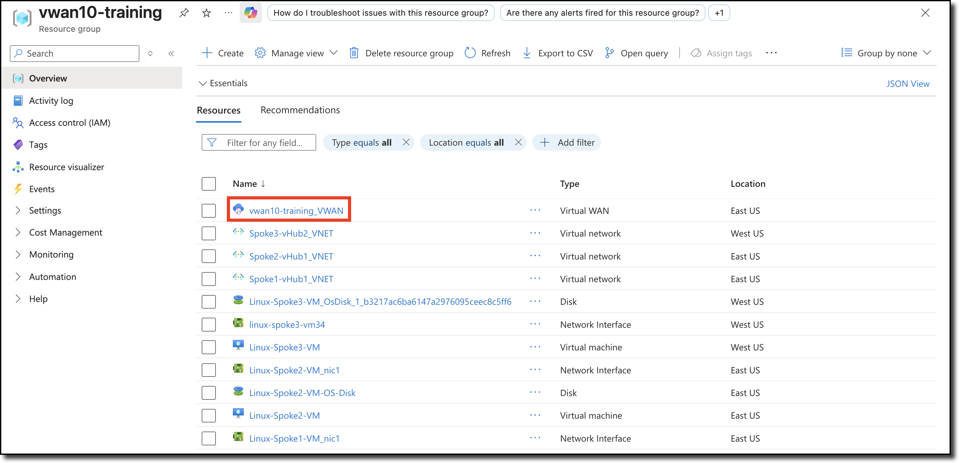
Click your Resource Group named vwanXX-training. XX is the number of your allocated environment.
Tip
In an Azure environment there can be many Resource Groups, use the search field to find your Resource Group.
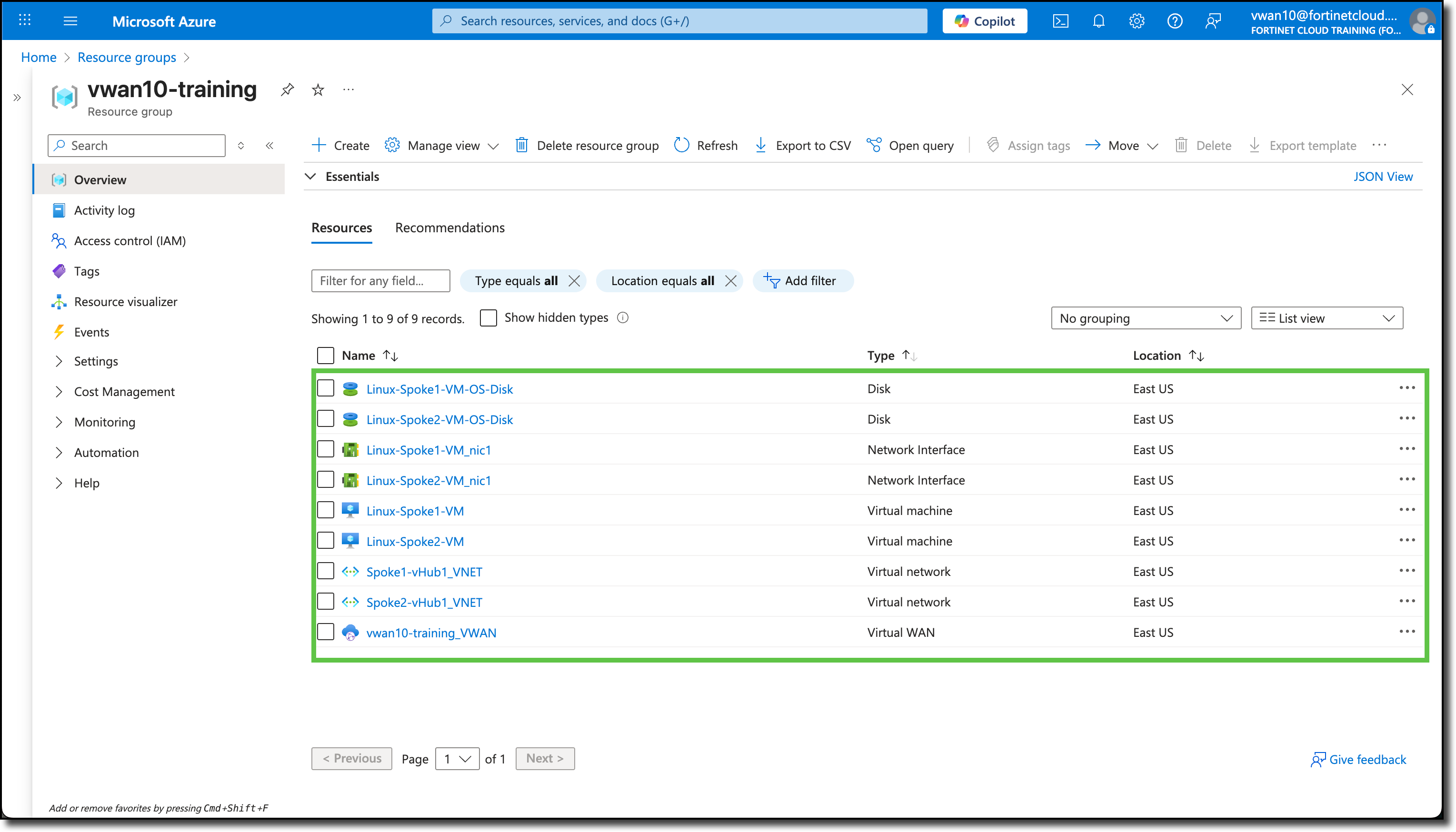
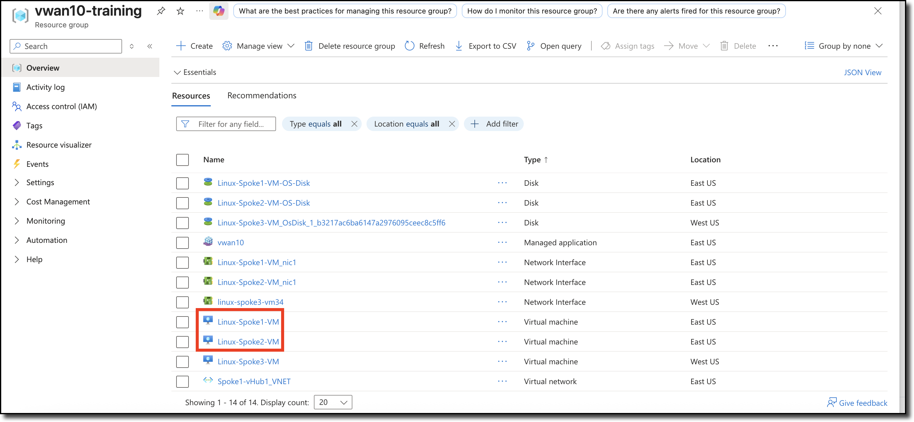
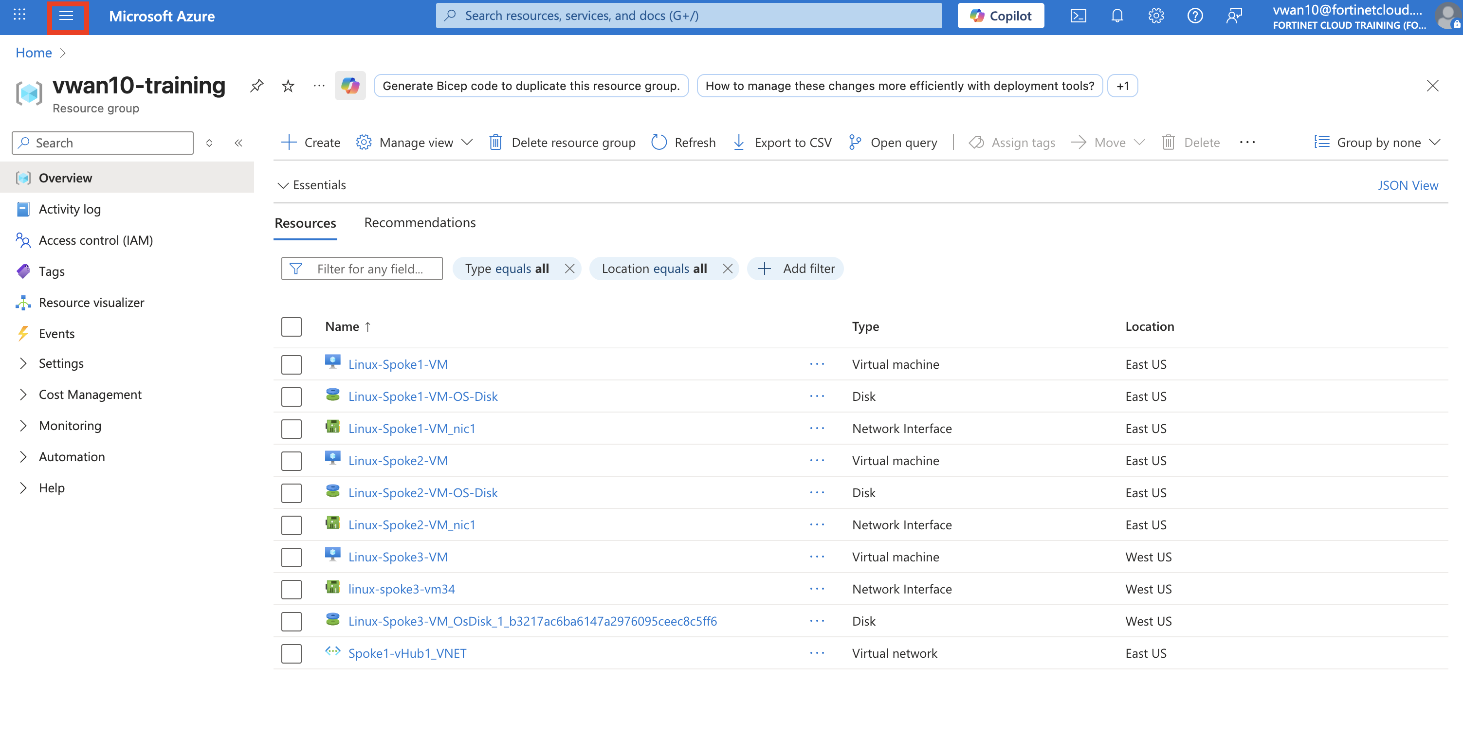
View the already deployed resources already deployed
Info
The assigned Resource Group has already been deployed along with the key resources for this session.
Review and make sure all the following resources are deployed in your resource group.
Virtual WAN (VWAN)
vwanXX-training_VWAN
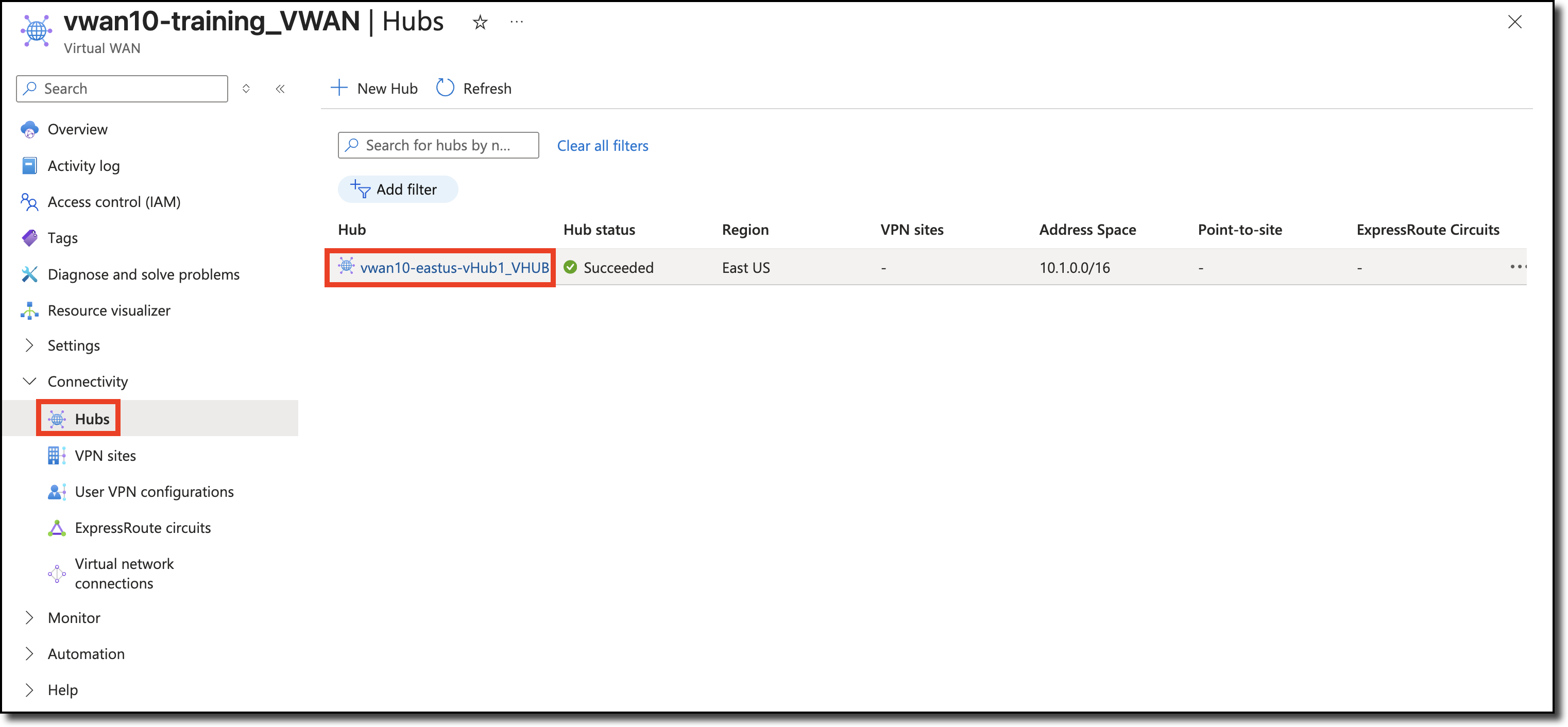
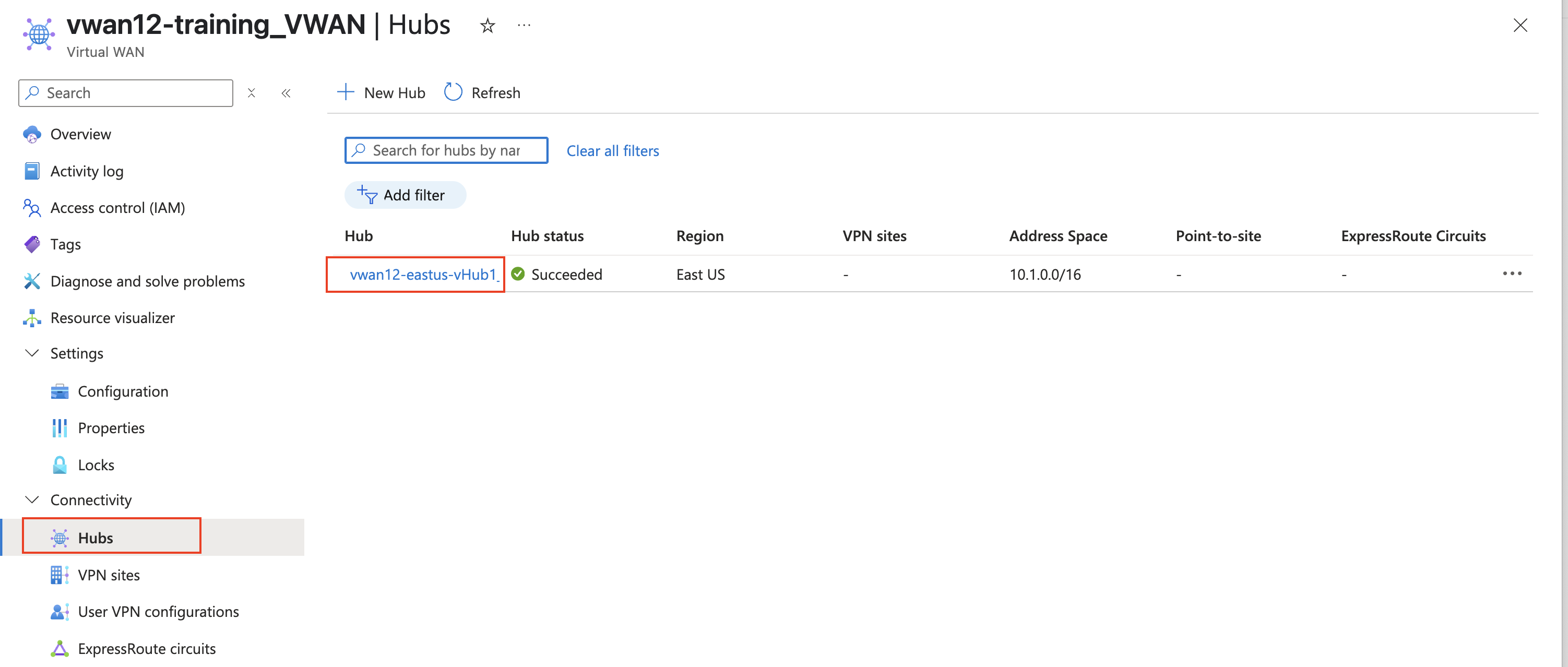
Virtual Hub (vhub) - This resource is visible in the vwanXX-training_VWAN page. Navigate to Connectivity then Hubs on the left side of the page.
vwanXX-eastus-vHub1_VHUB
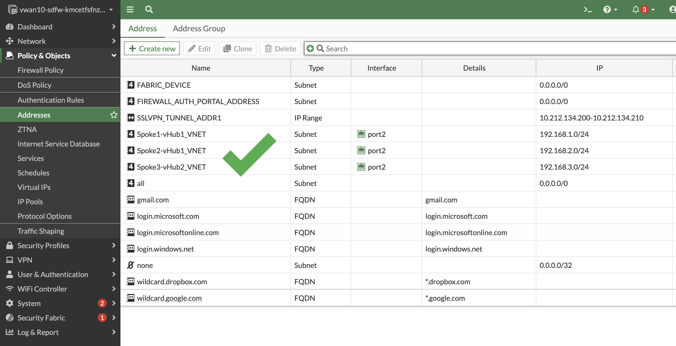
Virtual Networks (VNETs)
Spoke1-vHub1_VNET
Spoke2-vHub1_VNET
Virtual Machines (VMs) with disk and network interface
Linux-Spoke1-VM
Linux-Spoke2-VM
Continue to Chapter 4 - Securing the Azure vWAN
Chapter 4: Securing the Azure vWAN
Goal
Gain Experience deploying FortiGate in VWAN
Task
Deploy FortiGate in VWAN and configure FGSP once deployed, test VNET to VNET and Internet connectivity, configure BGP, enable Routing Intent, and peer VNETs with the vWAN hub.
Validation
FortiGate is deployed and connectivity to internet, VNET to VNET is working.
In this chapter, navigate to the assigned vWAN hub and deploy a pair of Fortigate NVAs to secure the vWAN. After the FortiGates have been deployed, configure FGSP, test VNET to VNET and Internet connectivity, configure BGP, enable Routing Intent, and peer VNETs with the vWAN hub.
Overview
Deploy FortiGate NVAs into assigned VWAN hub
Configure FGSP on both FortiGate NVAs
Confirm no VNET to VNET or Internet connectivity
Configure BGP and enable Routing Intent
Peer VNETs with the vWAN hub
After you have completed the above tasks, the diagram below is a visual representation of what you will have deployed and configured.
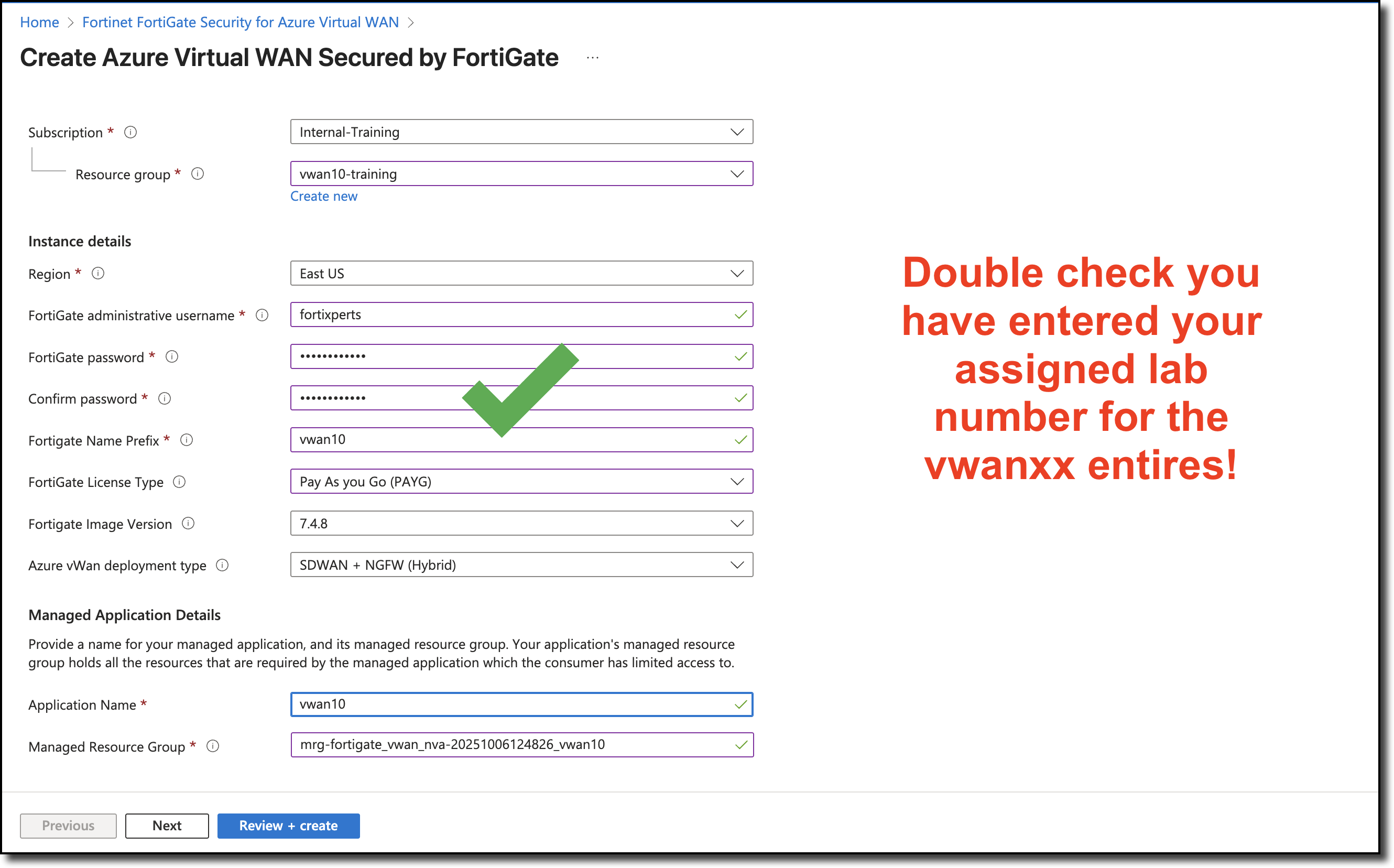
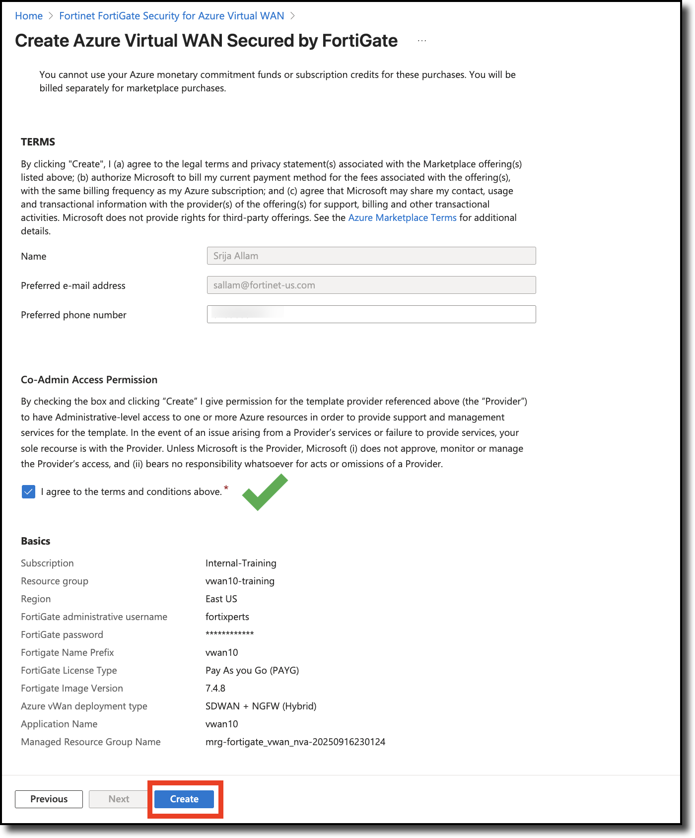
Enter - Application Name - vwanXX – Enter your assigned lab number for XX.
Update - Managed Resource Group - Append “_vwanXX” to the provided name – Enter your assigned lab number for XX.
Click - “Next”
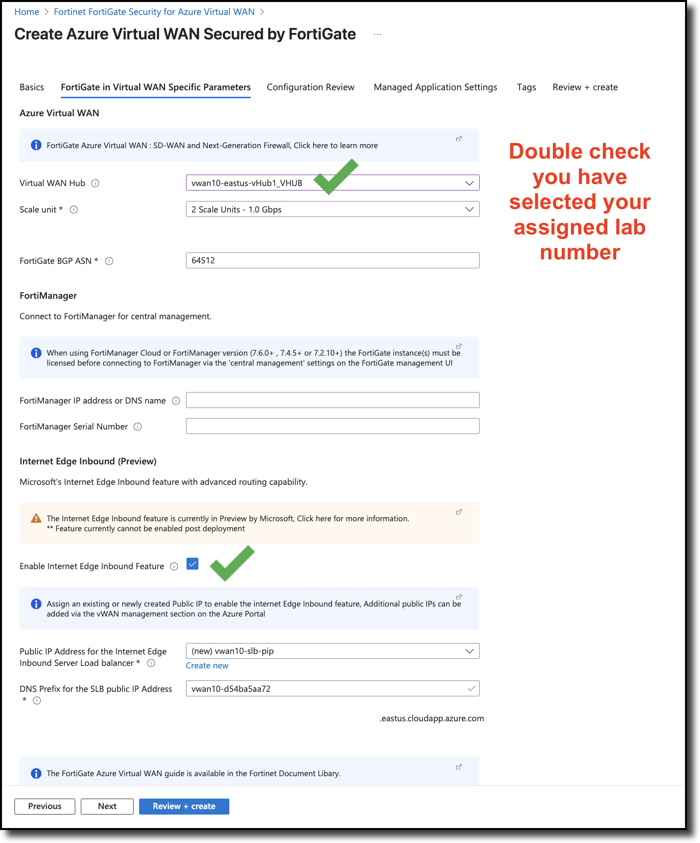
On the FortiGate in Virtual WAN Specific Parameters tab, enter the following values:
Select Virtual WAN Hub - select vwanXX-eastus-vHub1_VHUB – Be sure to enter your assigned lab number for XX.
CheckboxEnable Internet Edge Inbound Feature
Leave all other items as is
Click “Next”
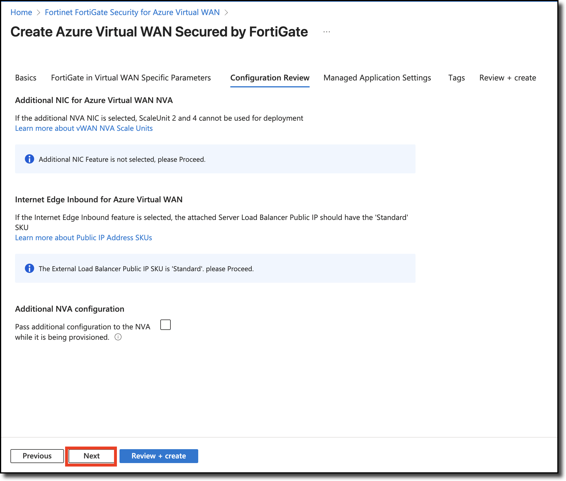
On the Configuration Review tab, select “Next”.
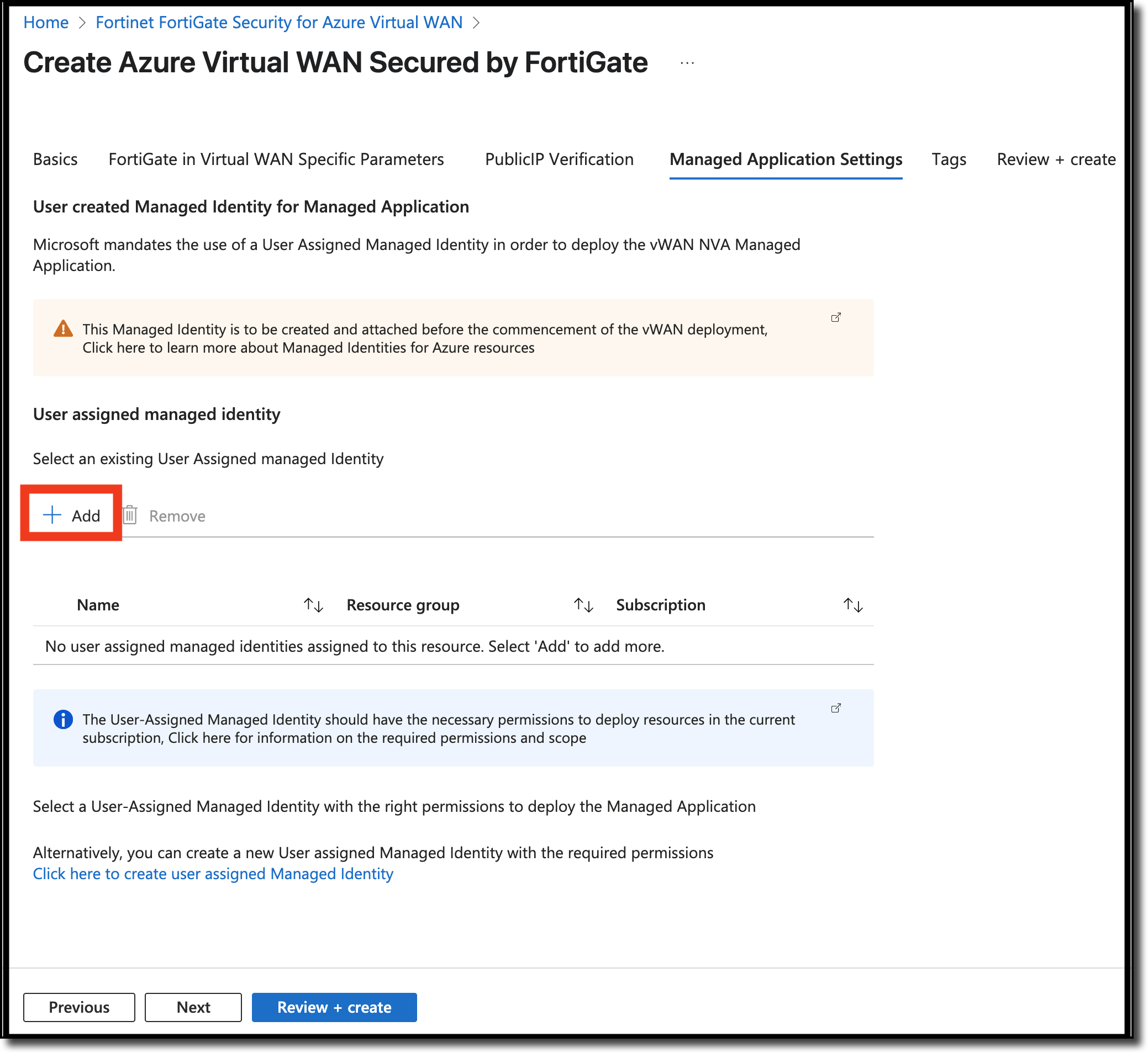
on the Managed Application Settings tab, click “Add”
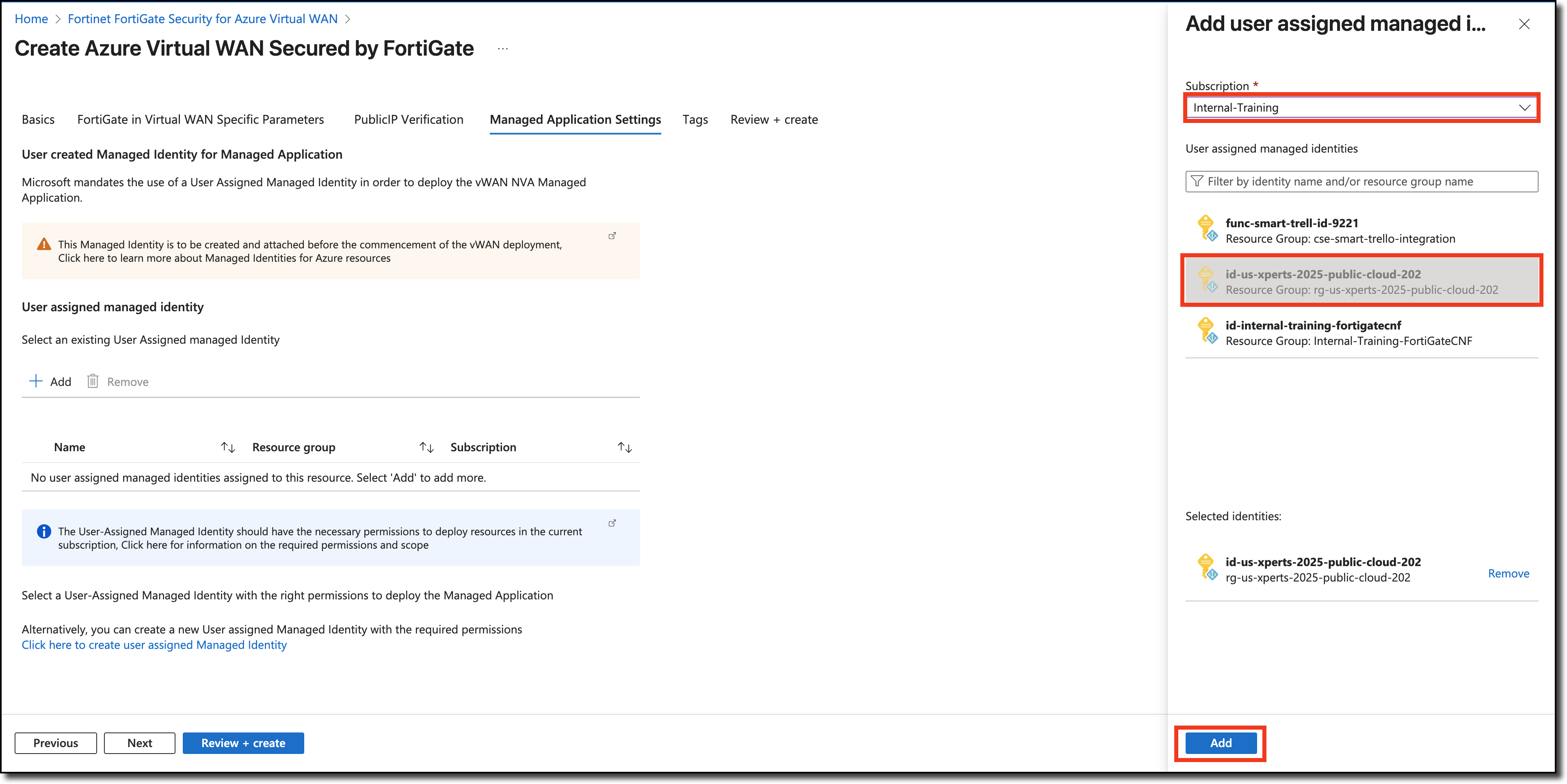
on the add User assigned managed identity,
Select Internal Training
Selectid-us-xperts-2025-public-cloud-202
Click “Add”
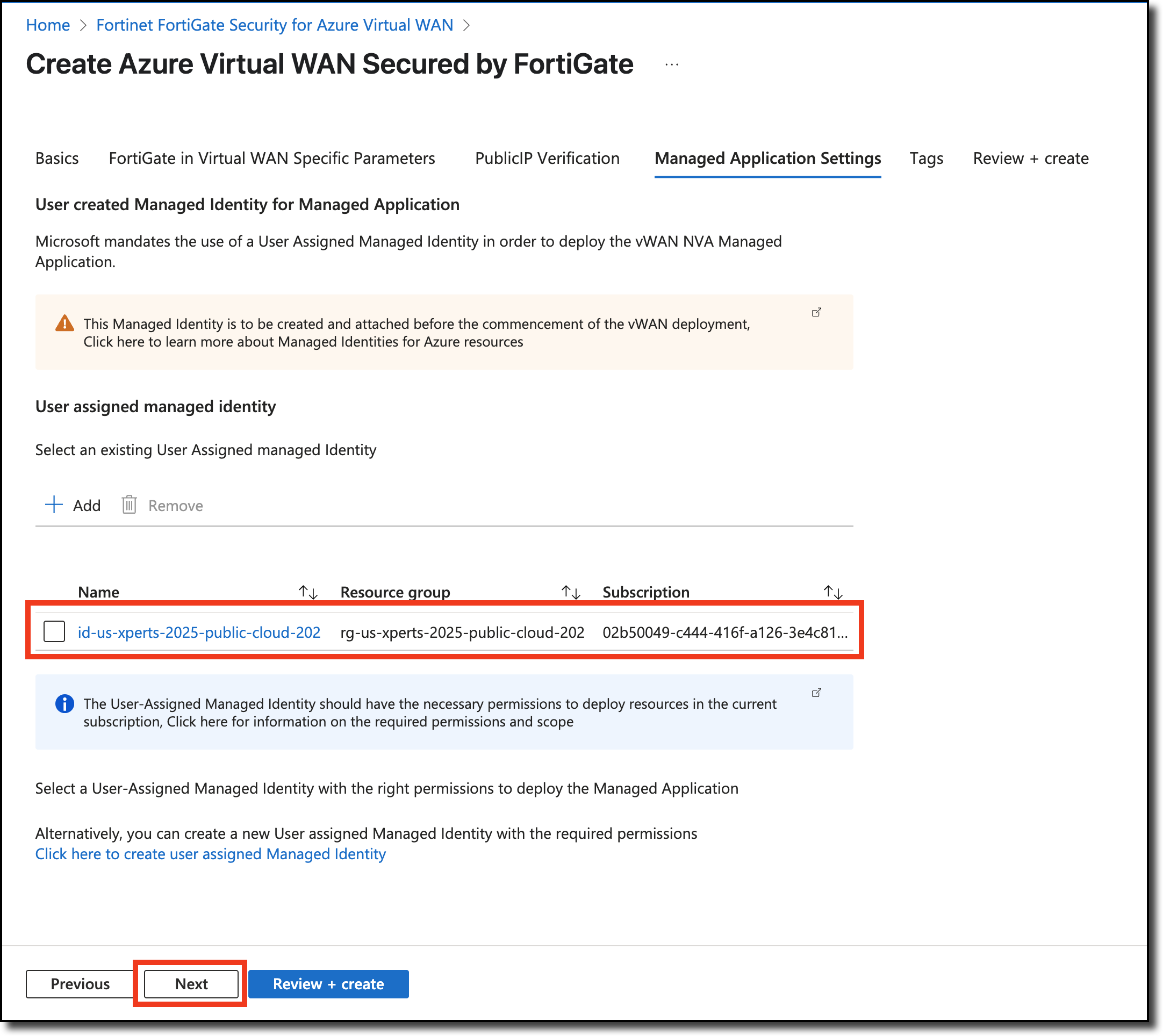
on the Managed Application Settings tab, make sure to verify it looks like below, click “Next”
On the Tags tab, select “Next”.
No screenshot included in this step
On the Review + create tab, select the following:
Scroll down to agree to the terms and conditions
Click “Create”
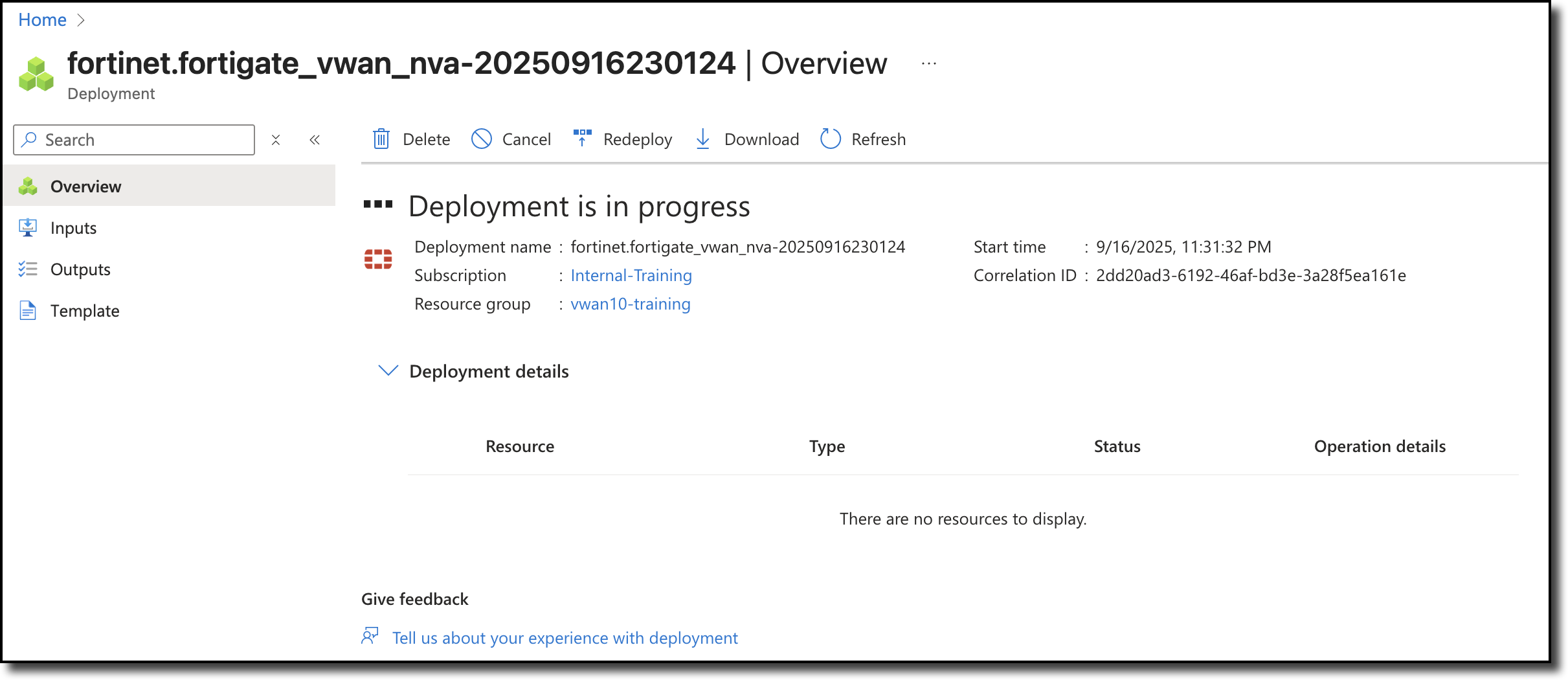
Info
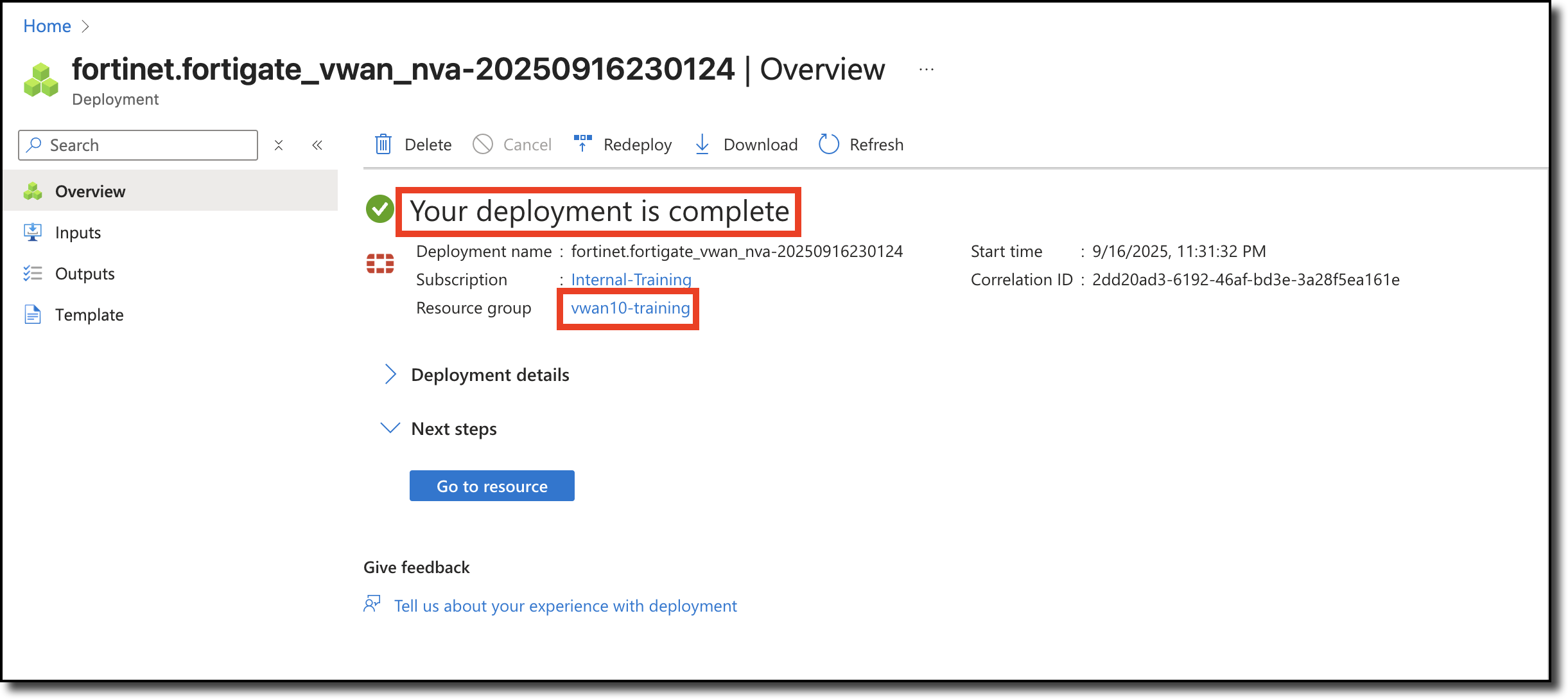
The FortiGate NVAs take about 15 minutes to deploy. Grab a refreshment and relax! You will see the screen belows when the deployment is in progress and when complete.
Click on your assigned Resource Group to return to your Resource Group and prepare for the next task.
Continue to Chapter 4 - Task 2: Configure FGSP
Task 2: Configure FGSP
After the FortiGate NVA deployments are complete, the next step is to configure FortiGate Session Life SupportFGSP on both FortiGates to enable session sync to support the Active-Active architecture.
Tip
You will open a browser session to each FortiGate, the FortiGate GUI defaults to a 5 minute “Idle timeout”. Avoid continually logging in by setting the idle timeout to 60 minutes in System–> Settings:Administration Settings:Idle timeout
To access the CLI on your FortiGate NVAs, following these steps:
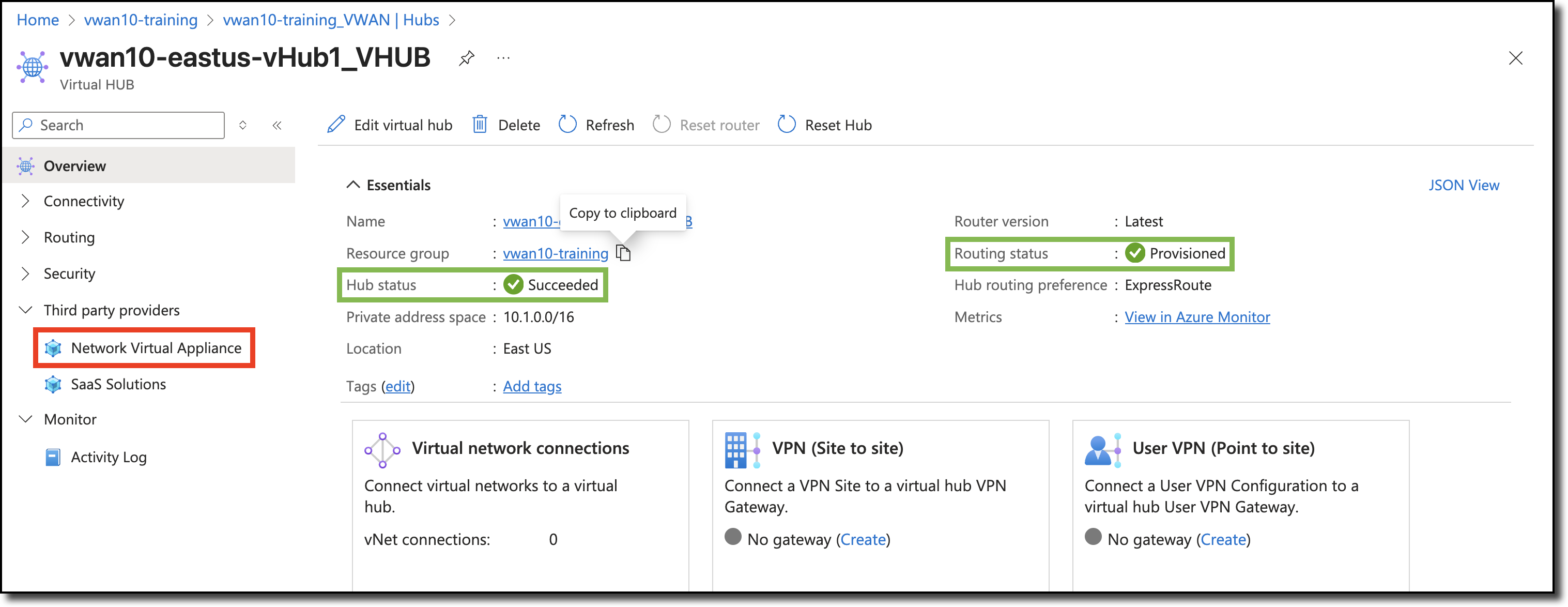
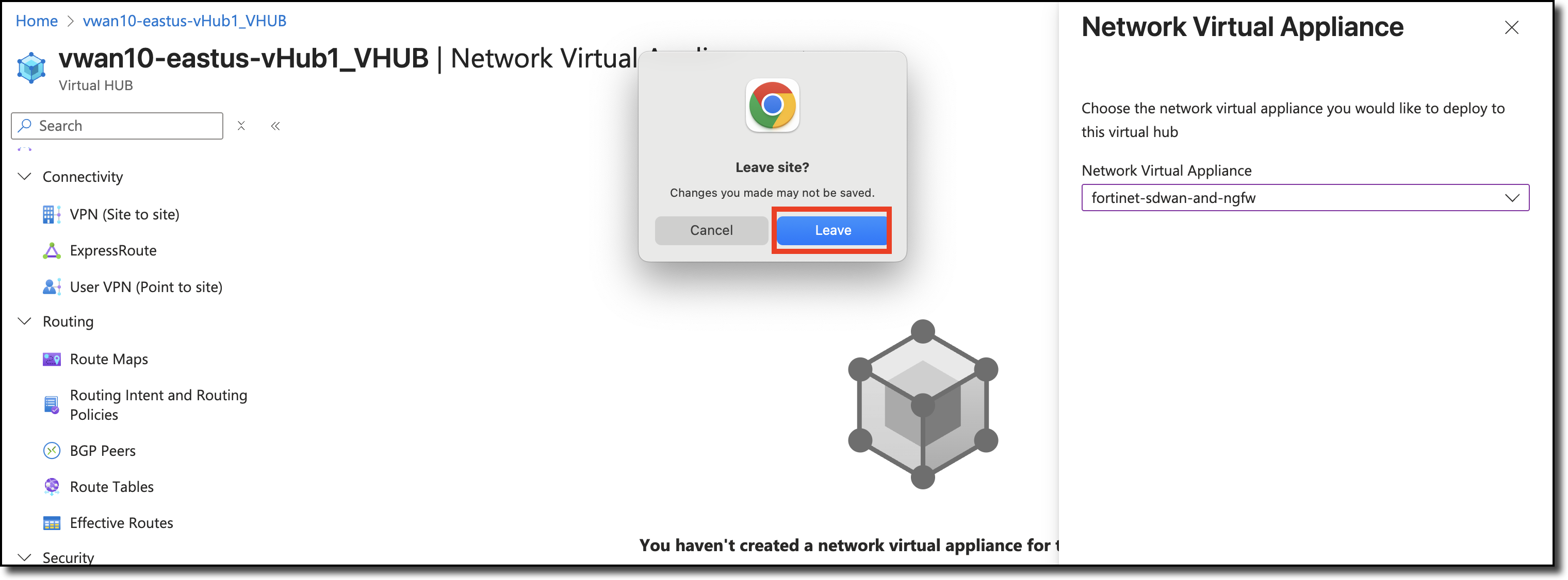
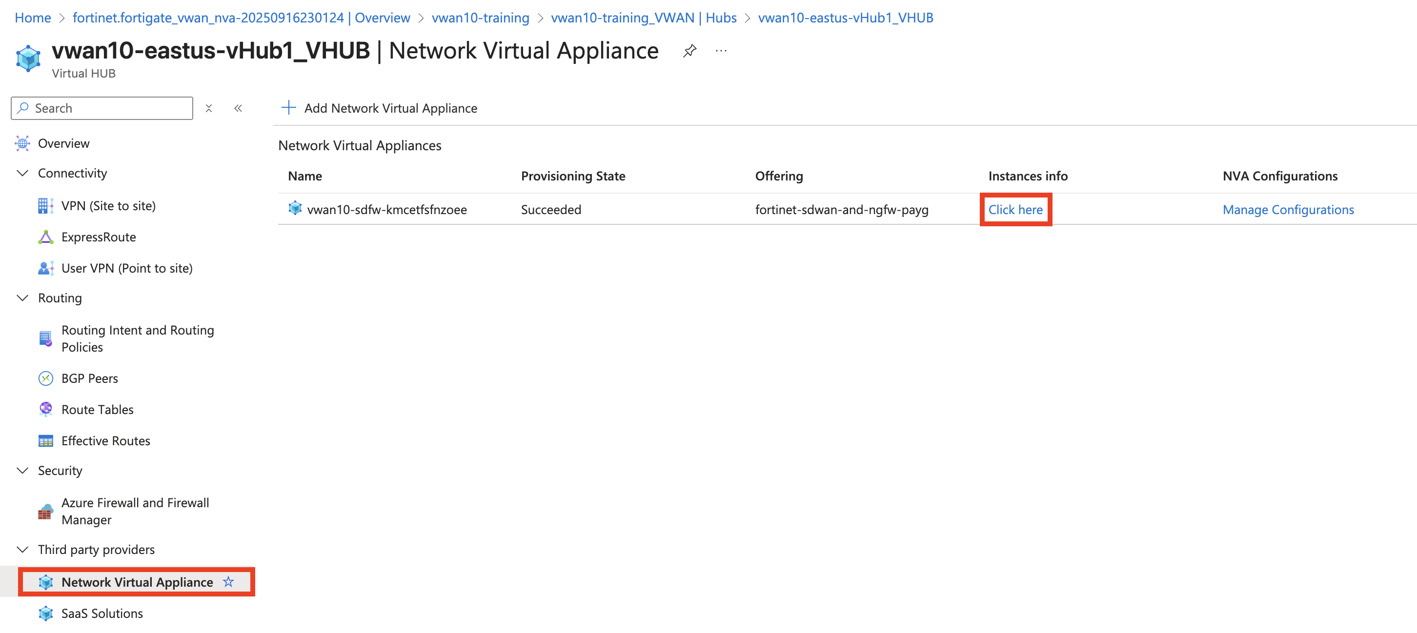
From your assigned Resource Group “vwanxx-training”, navigate to your vWAN “vwanxx-training_VWAN” and then your hub “vwanXX-eastus-vHub1_VHUB”
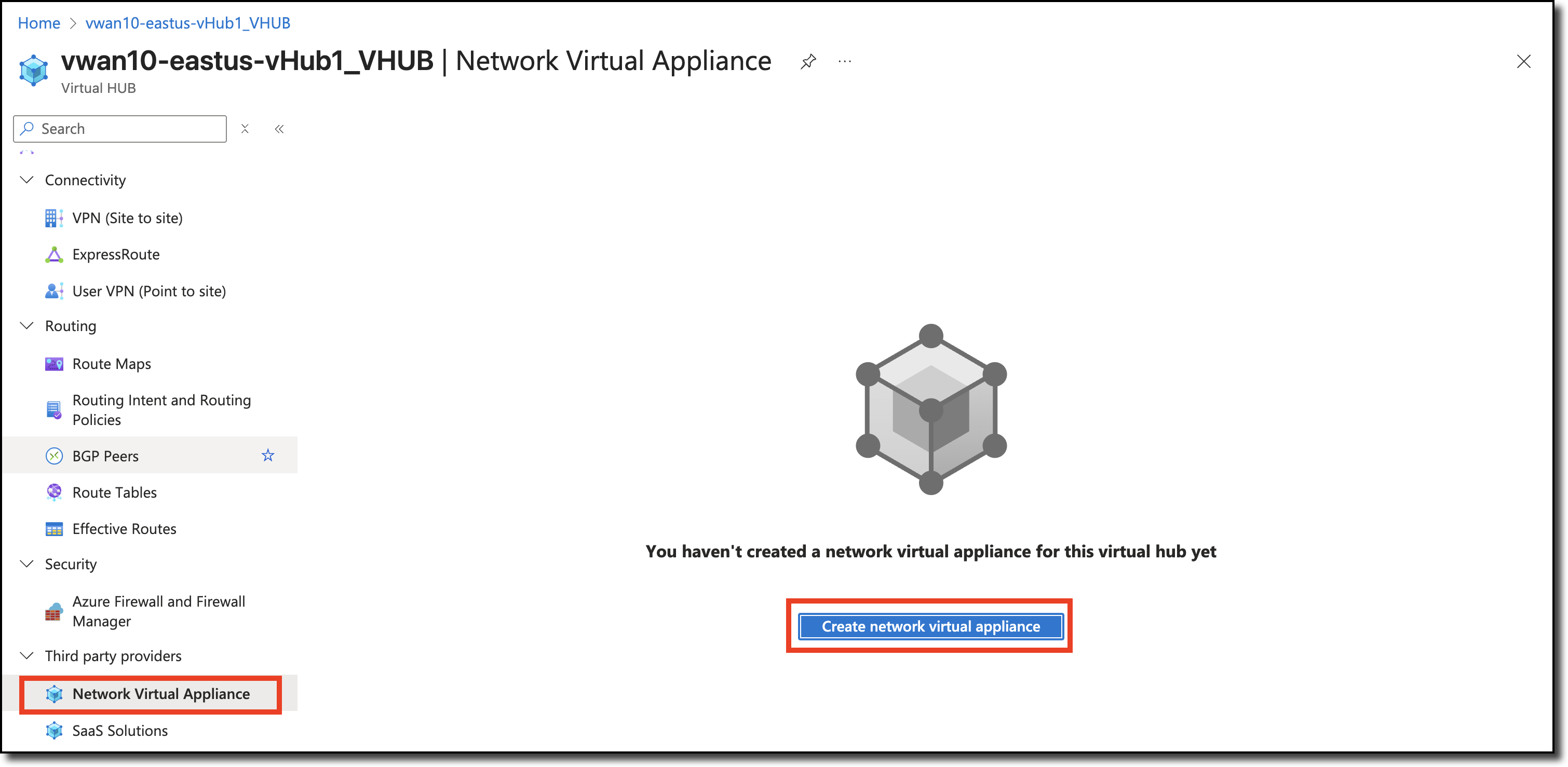
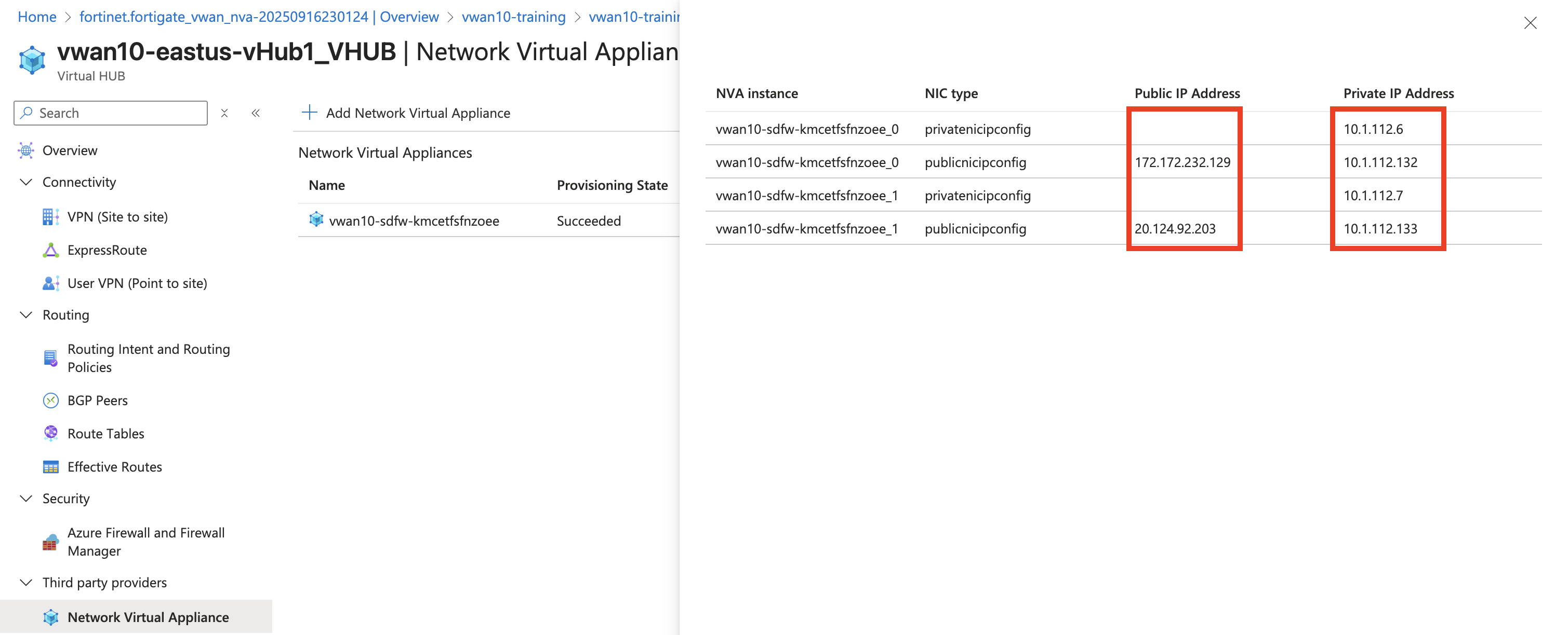
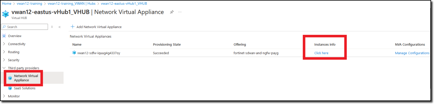
Click Network Virtual Appliance in the left-hand navigation
Click “Click here” link under “Instances info” in the right-hand “Network Virtual Appliances” pane
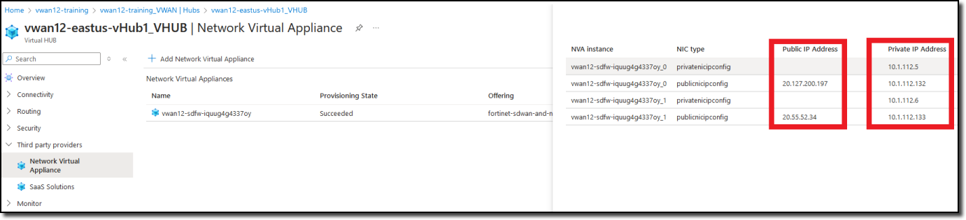
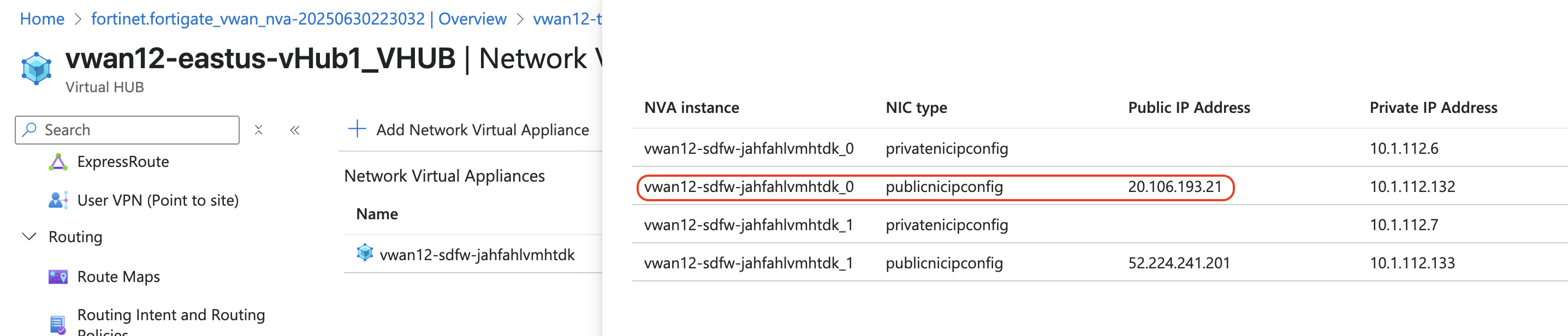
Note FortiGate Public IP and Private IP addresses
Open a browser tab to each FortiGate using the Public IP address of each FortiGate
Configure FGSP
Open a CLI session on each FortiGate
Enter the blocks of CLI commands on each FortiGate.
On FortiGate ending with 000000 configure the peerip address with the port2 private IP address of the FortiGate ending with 000001.
Warning
If the IP address of port2 on FortiGate ending 000001 is not 10.1.112.7 replace the peerip below with the port2 private IP address of the FortiGate ending with _1Copy these CLI commands to notepad or similar tool to update the peerip address, if required.
Answer “y” to the “Do you want to continue? (y/n)” prompt
Changing standalone-group-id or group-member-id will potentially affect FGSP traffic.Please first make sure the member is isolated from FGSP cluster properly.Do you want to continue? (y/n)
On FortiGate ending with 1 configure the peerip address with the port2 private IP address of the FortiGate ending with 000000.
Warning
If the IP address of port2 on FortiGate ending 000000 is not 10.1.112.6 replace the peerip below with the port2 private IP address of the FortiGate ending with 000000Copy these CLI commands to notepad or similar tool to update the peerip address, if required.
Warning
Notice that the group-member-id is 2 in the CLI commands below
Answer “y” to the “Do you want to continue? (y/n)” prompt
Changing standalone-group-id or group-member-id will potentially affect FGSP traffic.Please first make sure the member is isolated from FGSP cluster properly.Do you want to continue? (y/n)
FGSP is now configured and the FortiGates will share session information.
Continue to Chapter 4 - Task 3: VNET-to-VNET Traffic
Task 3: VNET-to-VNET Traffic
To be part of an Azure Virtual WAN, Azure VNETs need to be peered to the Azure vWAN hub. Prior to VNETs being peered to a vWAN hub, virtual machines in the VNET will route their traffic based on Azure default routing services such as user defined routing (UDR) or routes advertised by an Azure Route Server.
Two spoke VNETs have been deployed in your assigned resource group, each with a Linux virtual machine (VM). The spoke VNETs are just stand-alone VNETs which means the Linux VMs in one spoke cannot communicate with Linux VMs in the other spoke without setting up VNET peering with the hub and configuring routing.
In this task confirm that each Linux VM cannot communicate between VNETs but can communicate to the Internet.
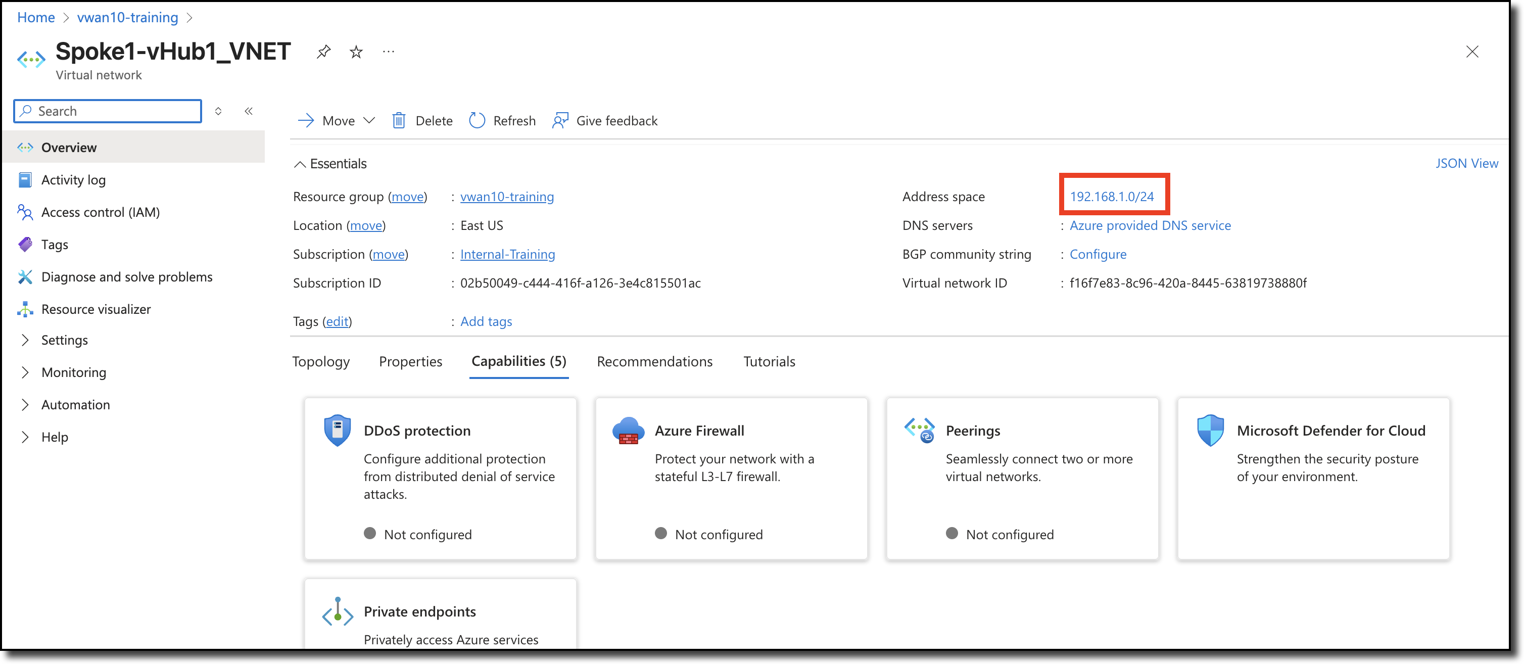
View the assigned VNET address space, navigate from your assigned resource group to each VNET
“Spoke1-vHub1_VNET”
“Spoke2-vHub1_VNET”
VNET assigned address space can be determined by clicking on a VNET and viewing the “Address space” value on the right side of the “Overview” pane.
VNET Spoke1-vHub1_VNET is shown below.
Repeat the above steps to determine the “Address space” for Spoke2-vHub1_VNET.
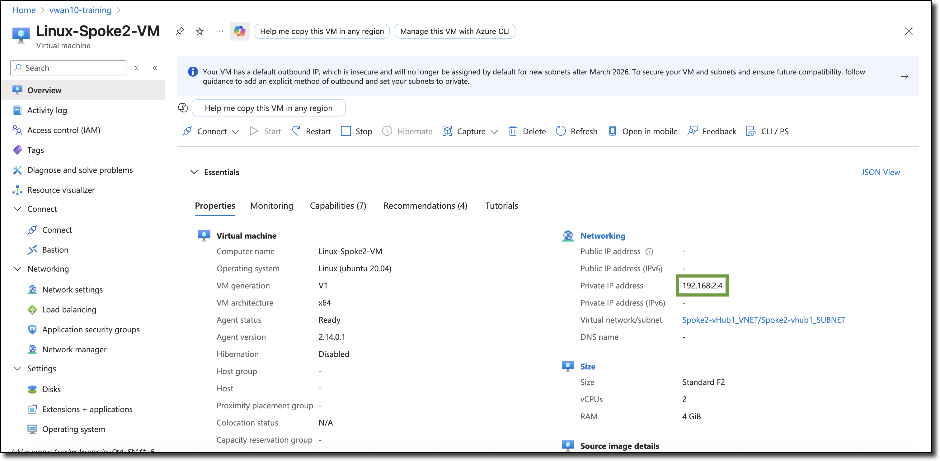
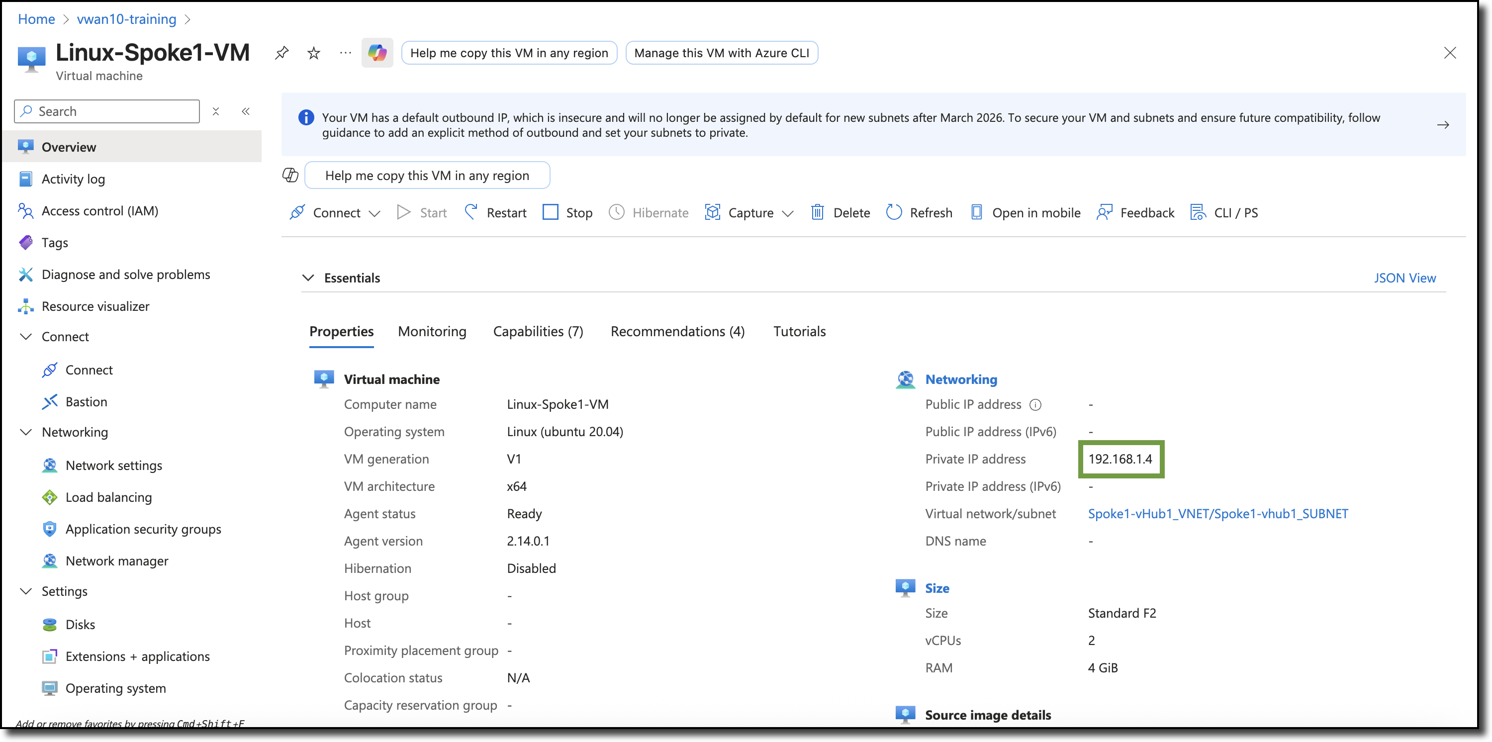
View the private IP addresses of the spoke VNET Linux VMs, navigate from your assigned resource group to each Linux VM - “Linux-Spoke1-VM” and “Linux-Spoke2-VM”.
Linux-Spoke1-VM
Linux-Spoke2-VM
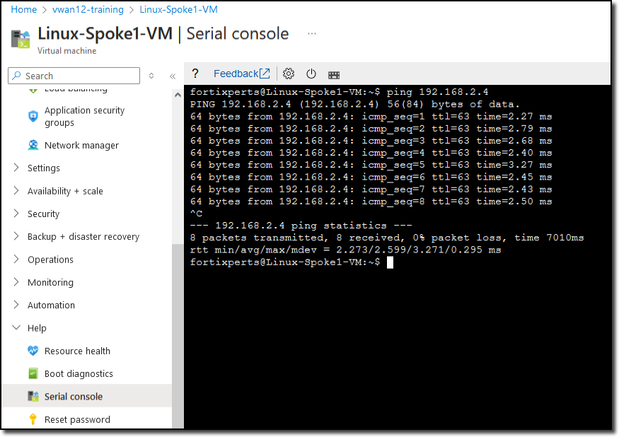
Access the serial console on the Linux-Spoke1-VM.
Scroll to the bottom of the left-hand navigation on the Linux-Spoke1-VM resource page
Expand the “Help” section (if not already expanded)
Click “Serial console”. A serial console session will start in the right-hand pane.
Login to Linux-Spoke1-VM:
username fortixperts
password fortiXperts!
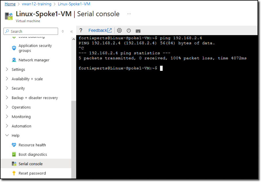
Ping Linux-Spoke2-VM from Linux-Spoke1-VM:
ping 192.168.2.4
PingLinux-Spoke1-VM from Linux-Spoke2-VM:
Repeat previous steps to access the serial console of Linux-Spoke2-VM
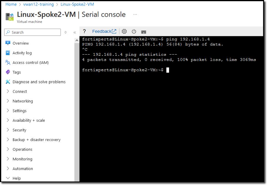
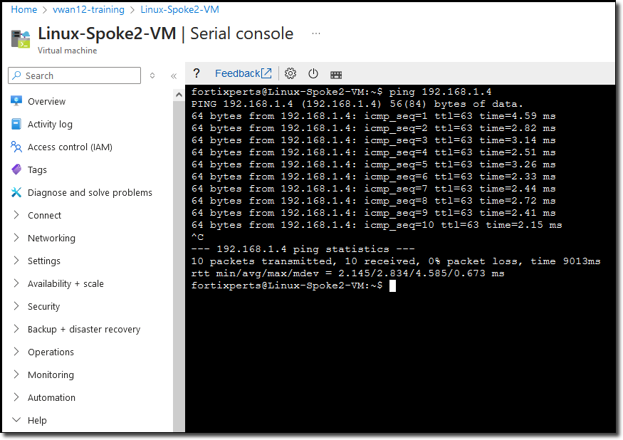
Ping Linux-Spoke1-VM from Linux-Spoke2-VM:
ping 192.168.1.4
wget the Fortinet home page both Linux VMs:
wget https://www.fortinet.com
Both ping tests will fail, these resources are unable to access each other however resources on the Internet are reachable.
In this task configure BGP on the FortiGates and enable Routing Intent from the Azure portal.
Configure BGP
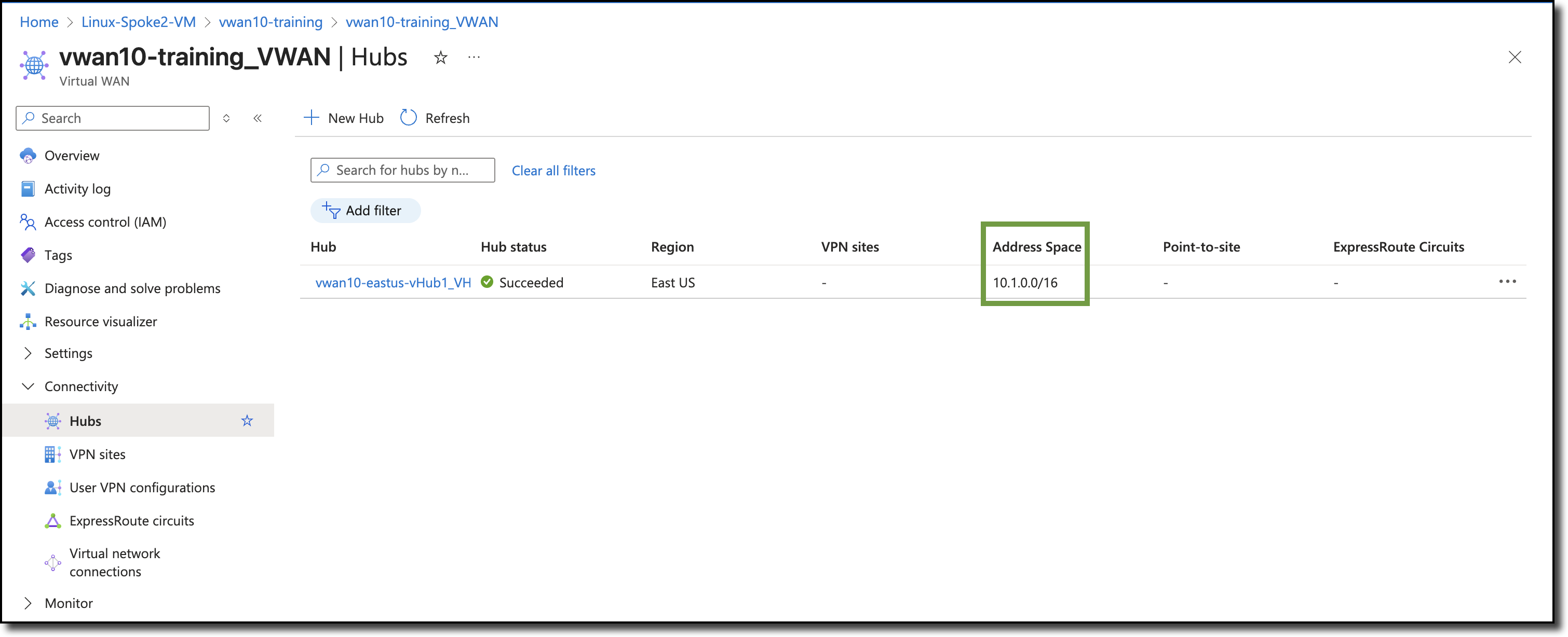
Confirm the private address space of the vWAN hub
The private address space of the vWAN hub is needed to create a summary route from the private address range to the secondary interfaces of the FortiGate NVAs to establish BGP peering.
The FortiGates are deployed with BGP peers already configured and ready to go online after the static route is enabled.
Navigate to your assigned hub vwanXX-eastus-vHub1_VHUB
View hub address space
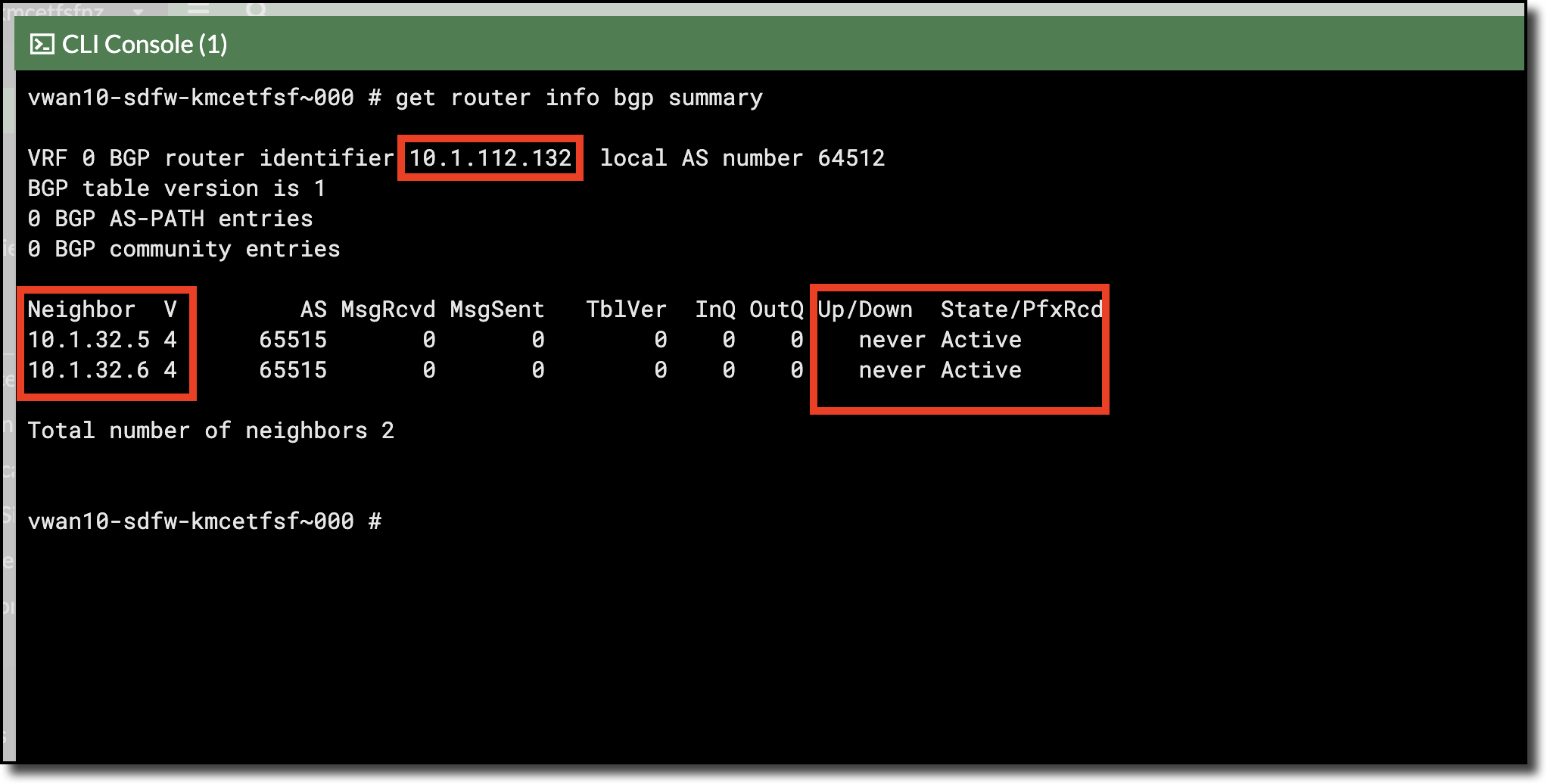
View FortiGate BGP peer status
Open each FortiGate in a browser tab/window
Open FortiGate CLI
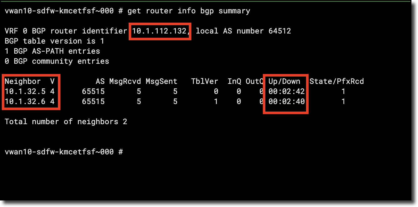
Run CLI command get router info bgp summary to view BGP Peer status
Determine FortiGate NVA port2 Gateway
Static routes are needed on the FortiGates to enable BGP, a component required to setup the static route is the gateway address of the FortiGate’s port2 interface.
Every subnet in Azure uses the first address in the subnet as the gateway. For example, in the subnet 10.1.1.0/24 Azure uses 10.1.1.1 as the subnet gateway.
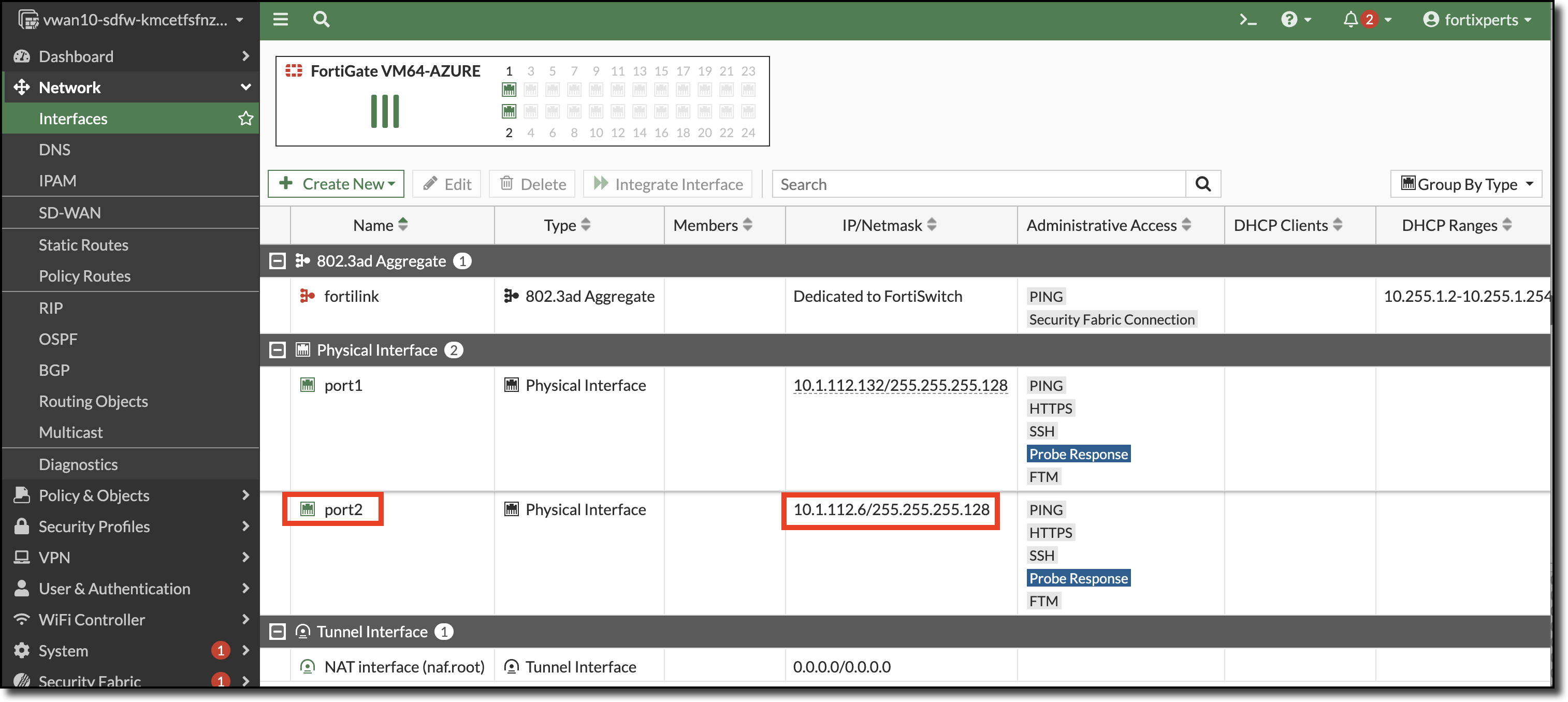
Click on Network
Click on Interfaces
View the assigned address of port2 and determine the gateway
In the screenshot below, the port2 IP address is 10.1.112.5/255.255.255.128 (/25)
Network address is 10.1.112.0
Gateway address is 10.1.112.1
Configure Static Routes on each FortiGate
Two static routes are required on each FortiGate
A static route to the virtual hub routers through the gateway of port2
A Static route for the internal Azure load balancer probes
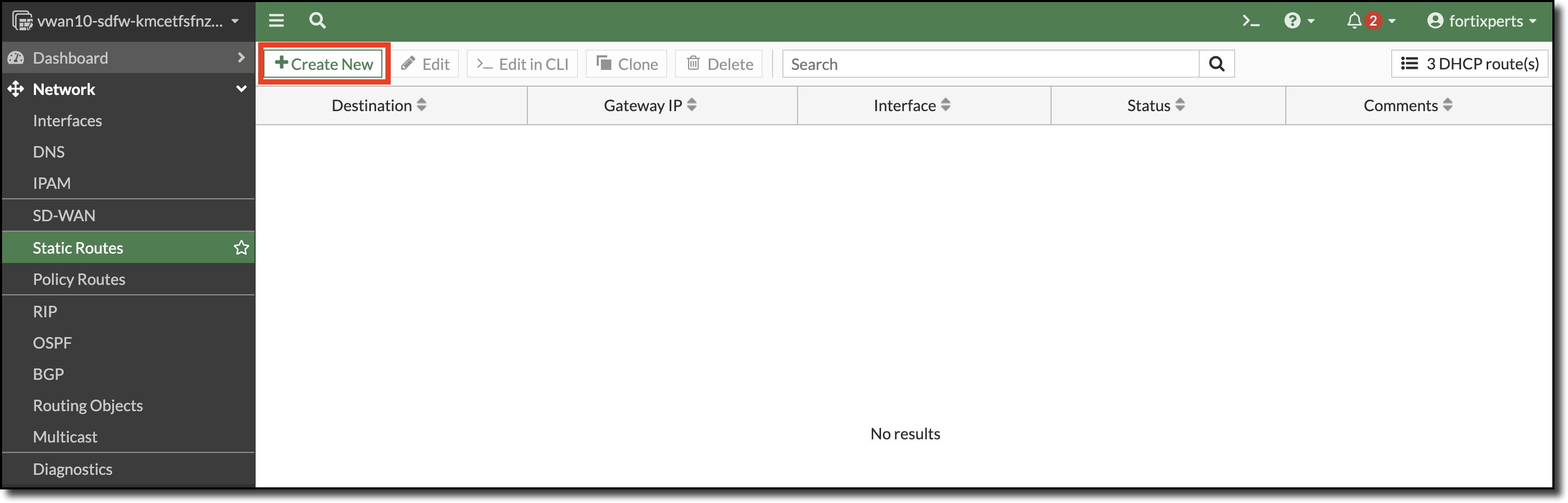
Click Network
Click Static Routes
Click Create New
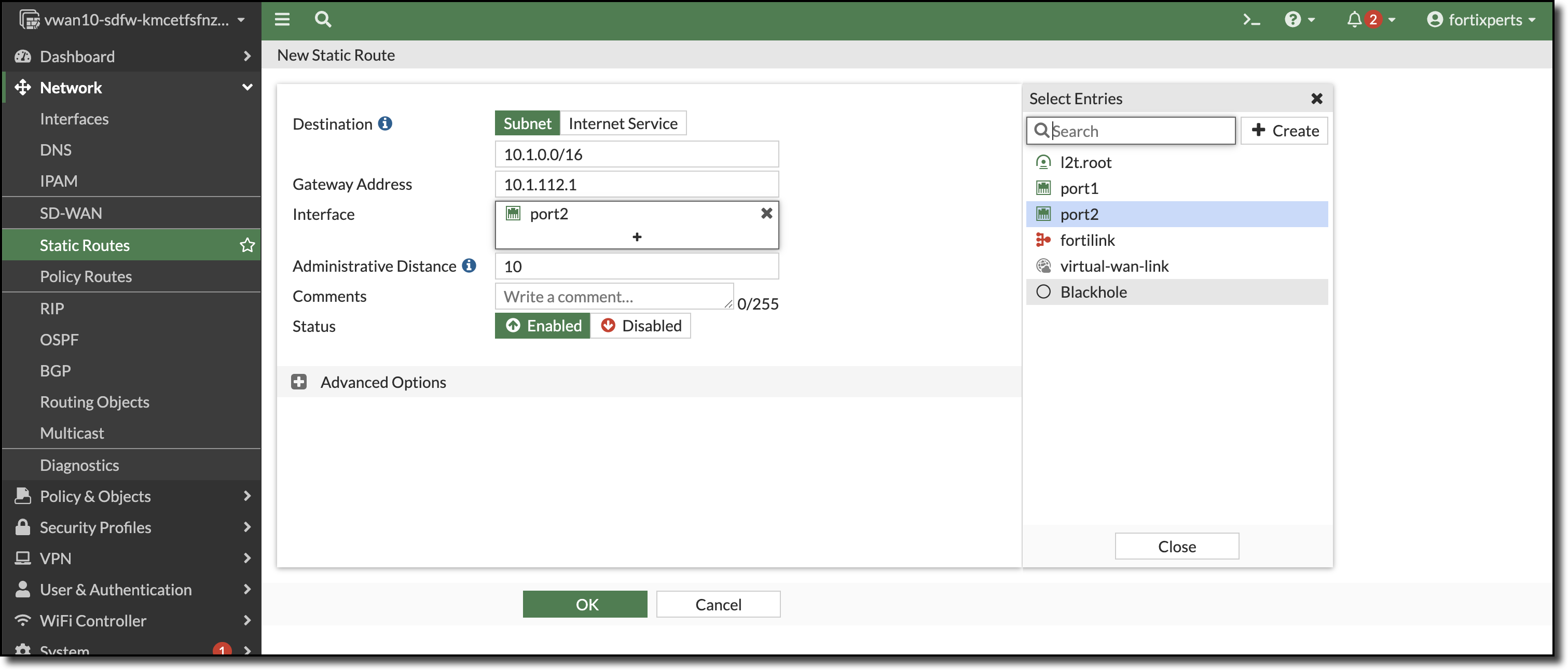
Create a static route
Enter Destination - 10.1.0.0/16
Enter Gateway Address - 10.1.112.1
Select Interface - port2
Click “OK”
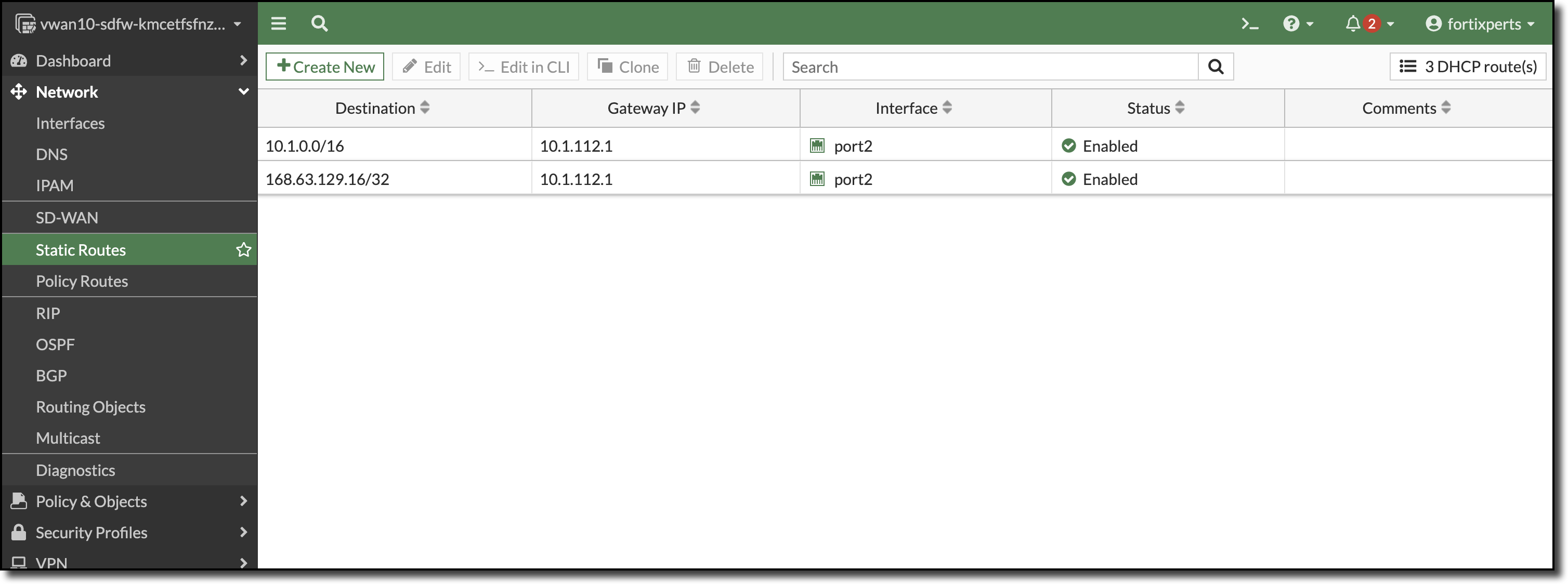
Repeat the process to add a static route for the Azure internal load balancer health probe
Refer to the overall architecturefor the internal load balancer placement.
Health probes enable the Azure load balancer to determine if a FortiGate is in a state to forward traffic.
The static route destination below is the default Azure load balancer health probe destination.
Enter Destination: 168.63.129.16/32
Enter Gateway Address: 10.1.112.1
Select Interface: port2
Enter Administrative Distance: 5
Click “OK”
Repeat the commands on the other FortiGate
CLI commands below can be used.
config router static
edit 1
    set dst 10.1.0.0 255.255.0.0
    set gateway 10.1.112.1
    set device "port2"
next
edit 2
    set dst 168.63.129.16 255.255.255.255
    set gateway 10.1.112.1
    set distance 5
    set device "port2"
next
end
When completed the static routes of each FortiGate should look similar to the screenshot below.
Verify BGP communication between FortiGate NVAs
After configuring the static routes on both FortiGates BGP peers are reachable.
Verify BGP communication between FortiGate NVAs in the CLI.
Open FortiGate CLI
Run CLI command get router info bgp summary
More information about FortiGate static routes and BGP can be found in Fortinet documents.
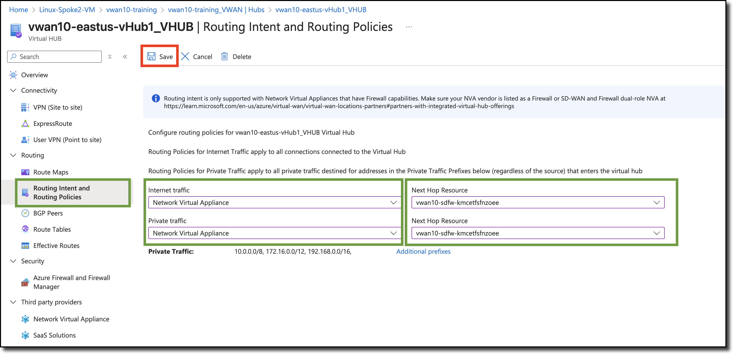
Enable Routing Intent
Routing Intent and Routing Policies allow you to configure the Virtual WAN hub to forward Internet-bound and Private (Point-to-site VPN, Site-to-site VPN, ExpressRoute, Virtual Network and Network Virtual Appliance) traffic to an Azure Firewall, Next-Generation Firewall Network Virtual Appliance (NGFW-NVA) or security software-as-a-service (SaaS) solution deployed in the virtual hub.
Enable Routing Intent
Navigate - to your Hub - vwanXX-eastus-vHub1_VHUB
Click - “Routing Intent and Routing Policies” on the left under “Routing”
Select - for “Internet traffic” - Network Virtual Appliance
Select - for “Private traffic” - Network Virtual Appliance
Select - for both “Next Hop Resources” - your cluster name (the only selection in the dropdown)
Click - “Save” to update Routing Intent
Continue to Chapter 4 - Task 5: VNET Peering and Verifying Routing
Task 5: VNET Peering and Verifying Routing
In this task setup peering between the spokes/VNETs and the vWAN hub.
Then second part of this task it to verify routing by viewing the routing tables on the FortiGate NVAs, the hub, and effective routes on the Linux hosts.
Peer Spoke VNETS to Hub
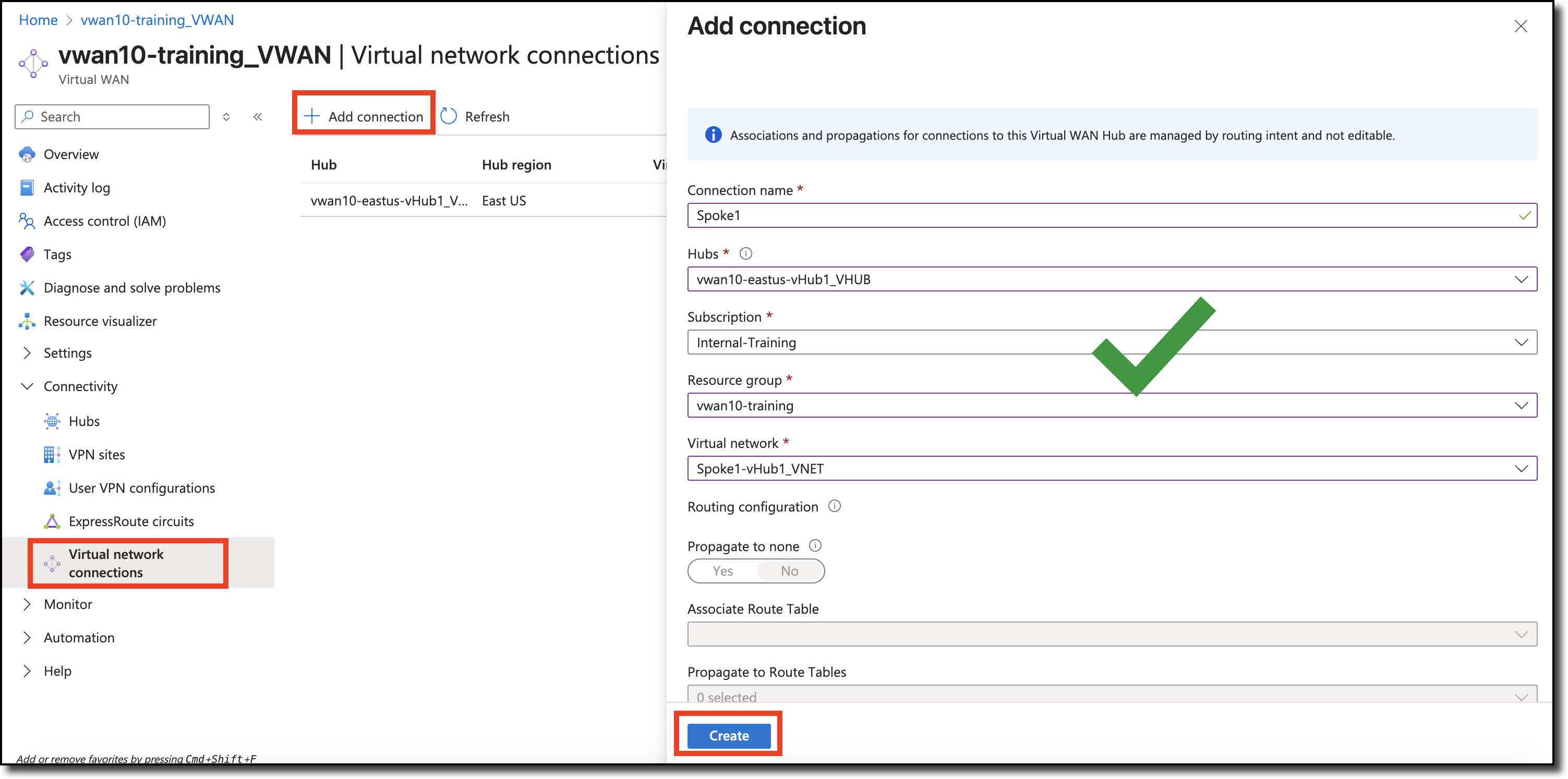
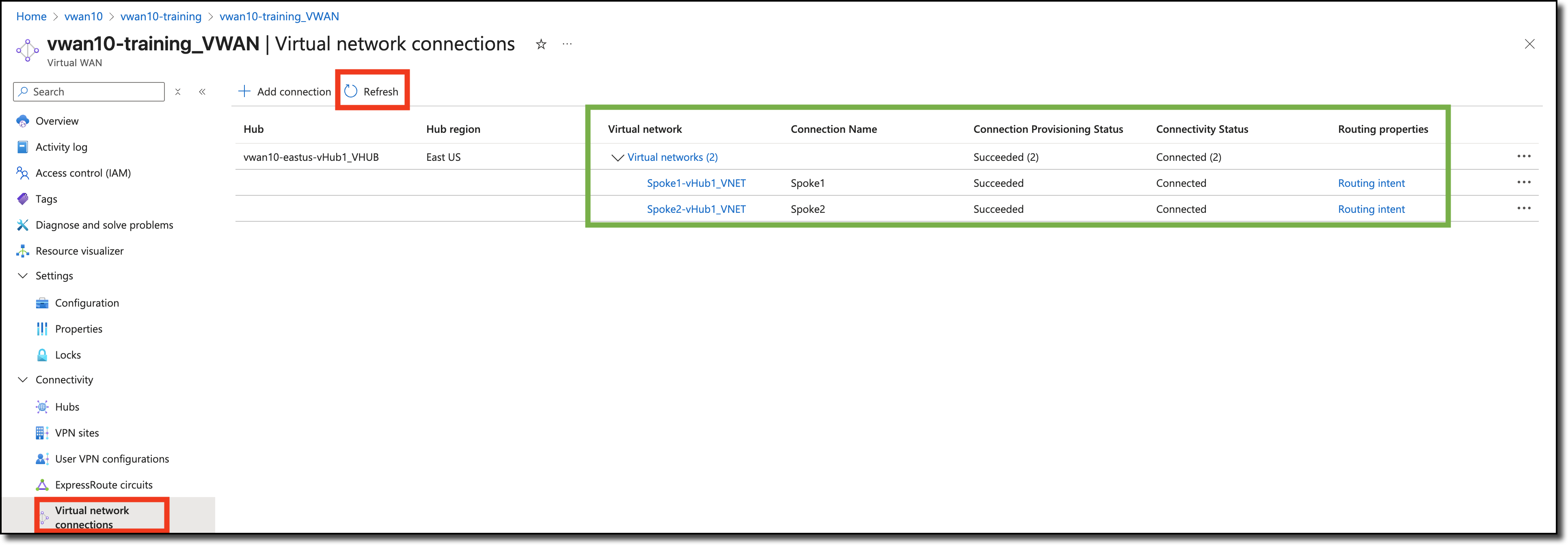
PeerSpoke1-vHub1_VNET to hub
Navigate to your Virtual Wan - vwanXX-training_VWAN
Click “Virtual network connections” on the left under “Connectivity”.
Click “+ Add connection”
Enter - “Connection name” - Spoke1
Select - “Hubs” - your assigned hub -vwanXX-eastus-vHub1_VHUB
Select - “Resource group” - your resource group - vwanXX-training
VNET Peering takes a few minutes to complete. The Connectivity Status can be reviewed by Clicking Refresh
Verify Routing
Routes and routing are the key for users to access workloads in an Azure VNET and for those workloads to be able to access resources outside of their VNET. At this point routes and routing should be set within the Azure environment and in the FortiGate NVAs.
From the perspective of the FortiGate, a decision will be made to send traffic to a specific port based on FortiGate policy. Once the traffic leaves the FortiGate’s port, it is up to Azure to forward the traffic.
Where traffic will be sent in Azure can be determined by viewing the effective routes associated to a particular networking service.
What routes do the FortiGates know about?
What are the effective routes of the hub?
What are the effective routes of the Linux VMs in the Spoke VNETs?
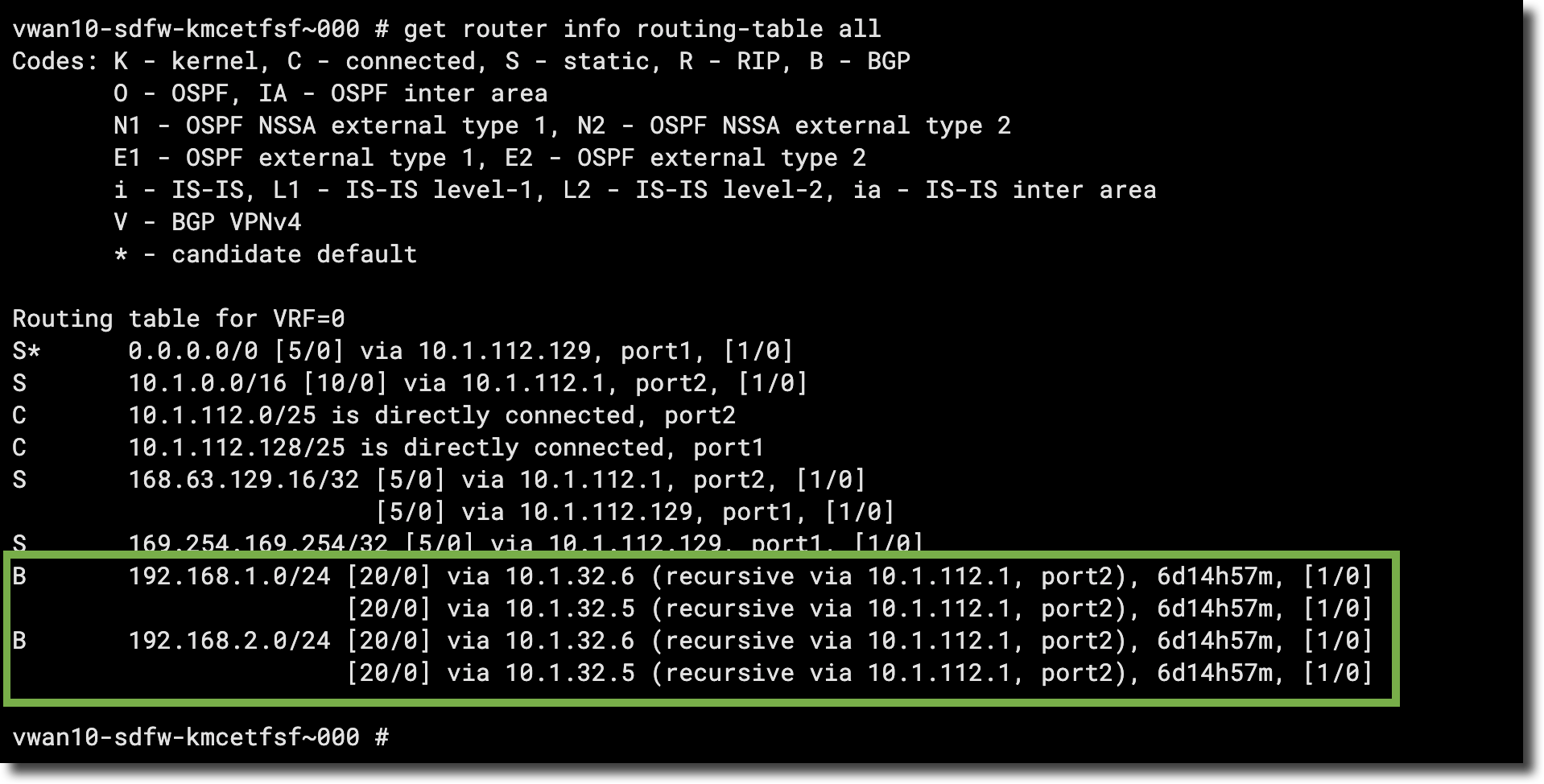
View each FortiGate’s route table
Open each FortiGate in a browser tab/window
Open FortiGate CLI
Run CLI command get router info routing-table all
The output shows that BGP routes have been learned for the two Spoke VNETs that were peered to the Hub
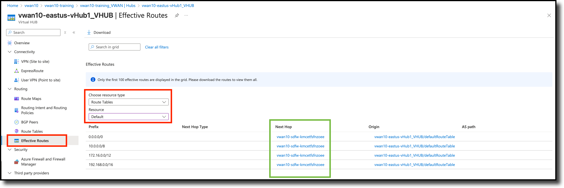
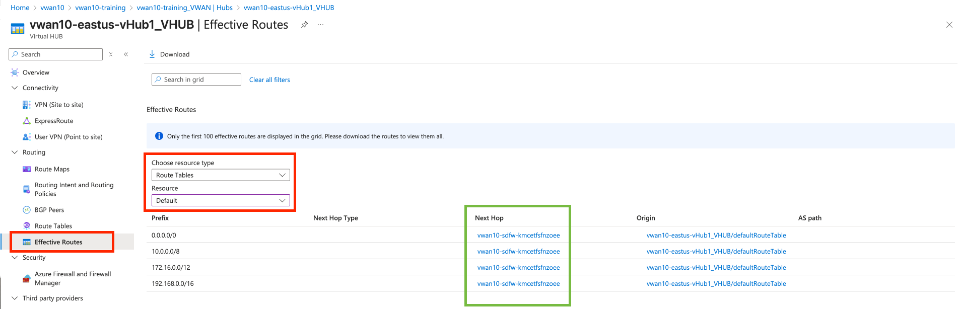
View the hub effective routes in the default route table
Navigate to your vWAN hub - vwanXX-eastus-vHub1_VHUB
On the left side, expand “Routing” and then “Effective Routes”
Select - “Route Tables” under “Choose resource type”
Select - “Default” under “Resource”
All effective routes should have the FortiGate NVA group as next hop.
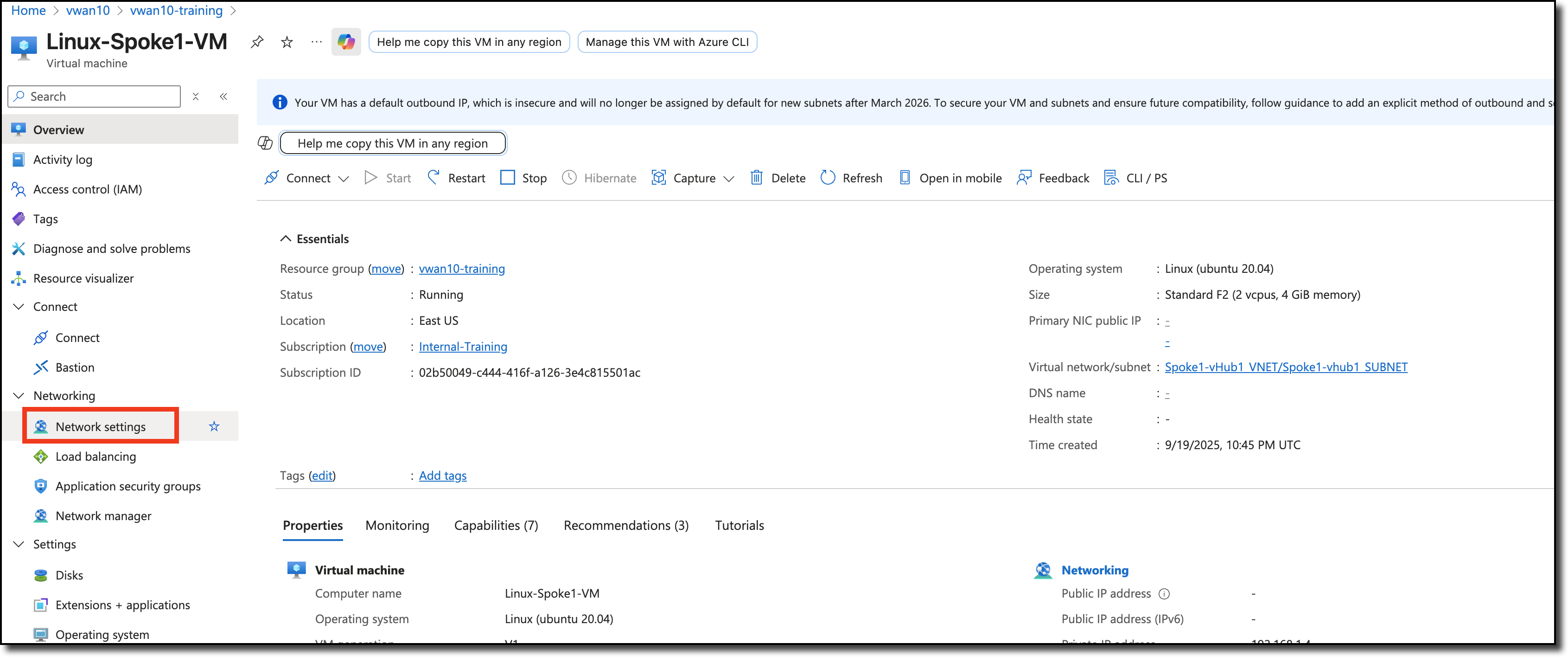
View the effective routes on the spoke Linux VMs
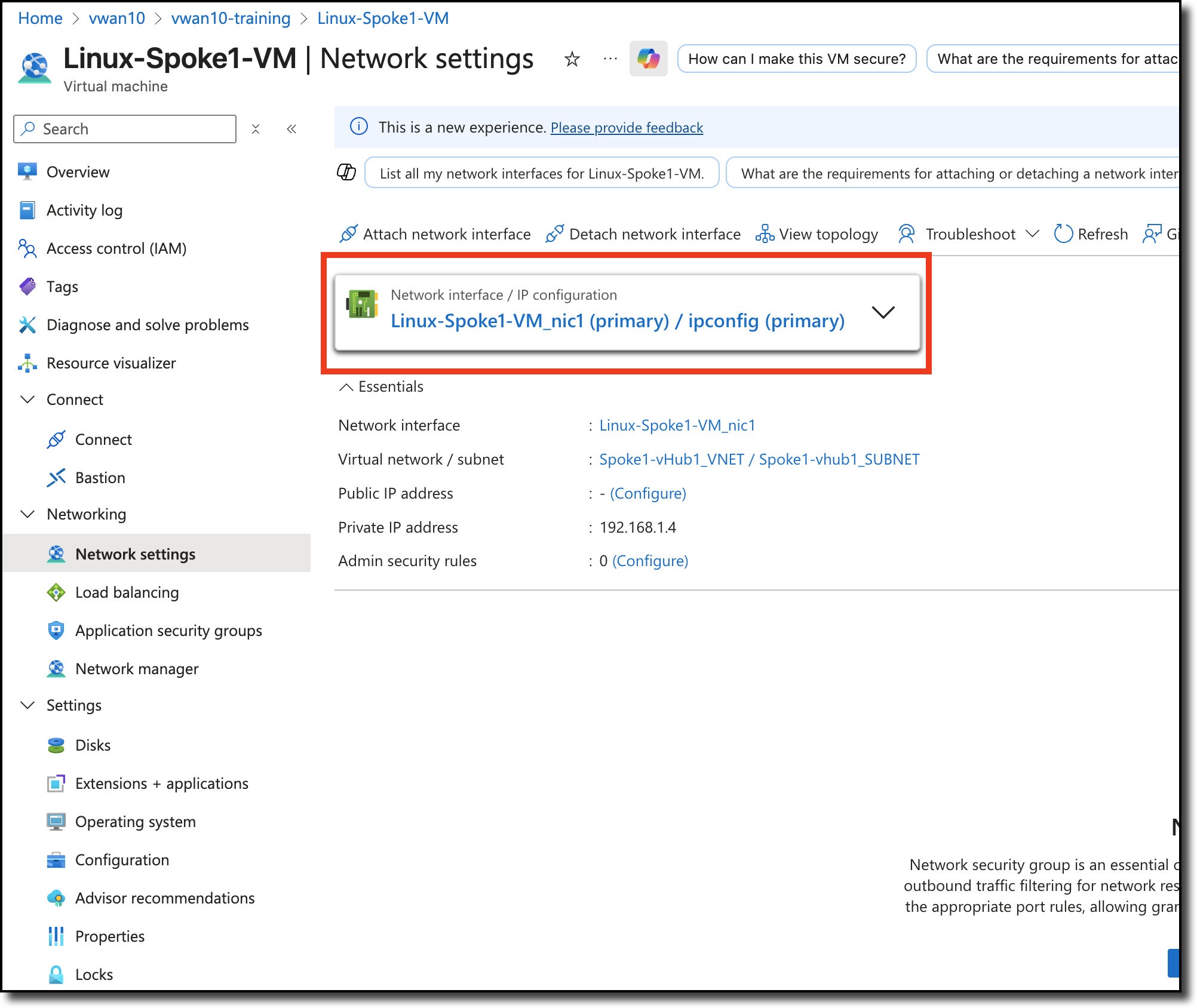
Navigate to your Linux VM Linux-Spoke1-VM
Click - “Network settings” located under “Networking” on the left side of the page
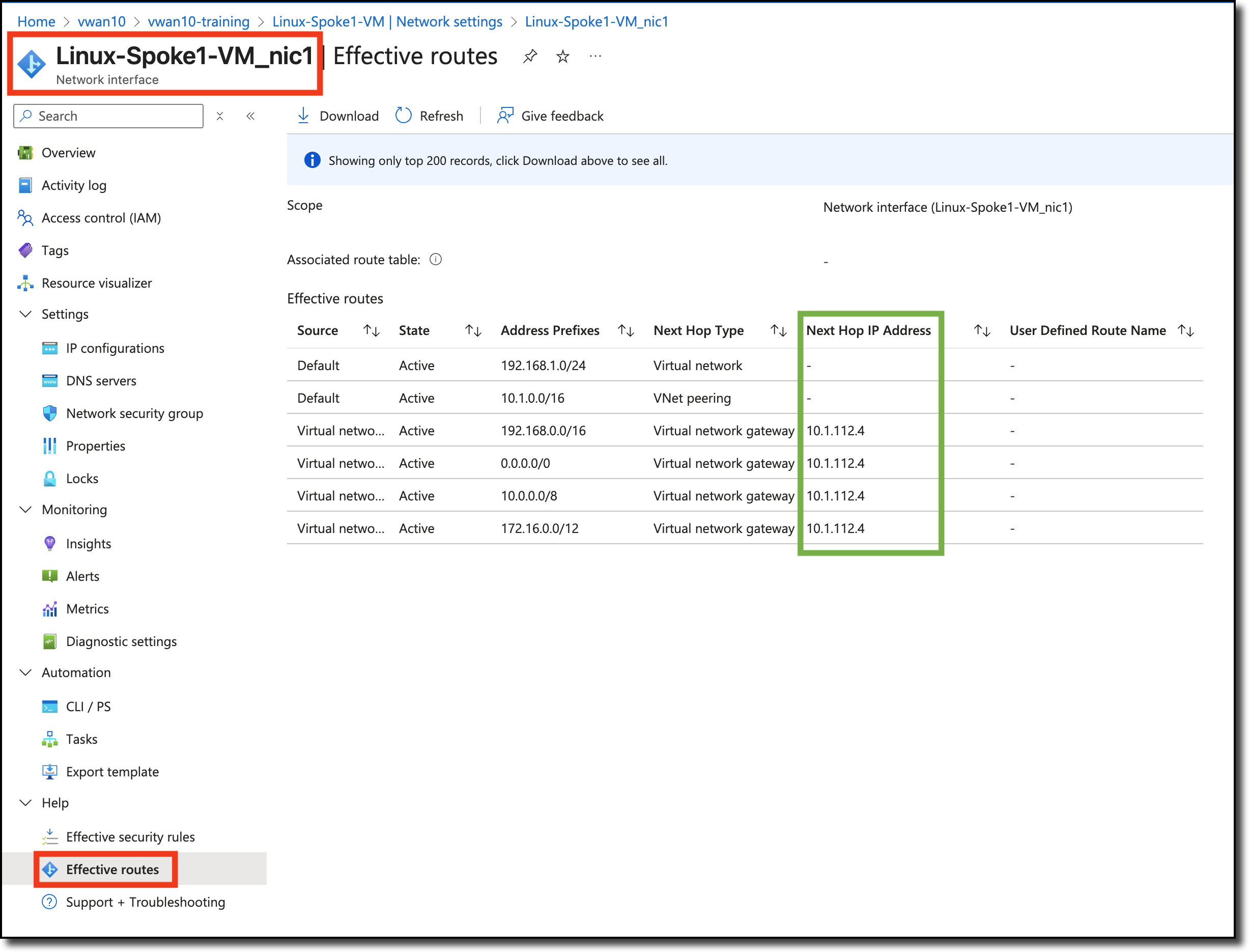
One the next page, navigate to Help on the bottom left and Click - “Effective Routes”
Repeat for Linux-Spoke2-VM
The effective route’s next hop IP is the IP address of internal load balancer that is deployed in the vWAN hub with the FortiGate NVAs.
The diagram below is a visual representation of what you have deployed and configured. Congrats!
Continue to Chapter 5 - Network Traffic Management
Chapter 5: Network Traffic Management
Goal
Gain Experience with managing traffic on FortiGate’s in VWAN
Task
Manage network traffic from spoke to spoke (East-West) and from spoke to the Internet (North/South) with firewall policies
Validation
Firewall policies are configured and traffic flows as expected.
In this chapter manage network traffic from spoke to spoke (East-West) and from spoke to the Internet (North/South). This will be accomplished by creating firewall policies on the FortiGate NVAs.
Progress Summary:
FortiGate NVAs have been deployed and FGSP configured
Azure Virtual Networks (the Spokes) have been peered with the vWAN hub
BGP and Routing Intent have been configured and enabled
Info
Commonly used tools curl, ping and wget can help determine availability and reachability of devices and services.
Additionally packet sniffing in the FortGate CLI can help determine if traffic is reaching the FortiGates for inspections and forwarding to the appropriate destination.
Continue to Chapter 5 - Task 1: East-West Network Traffic
Subsections of Chapter 5: Network Traffic Management
Task 1: East-West Network Traffic
In this task create FortiGate firewall policies to allow east-west network traffic.
Spoke to Spoke traffic (East-West)
Ping between Linux Spoke VMs.
Open a serial console connections to each Linux Spoke VM and ping the other Spoke VM
Linux-Spoke1-VM - ping 192.168.2.4
Linux-Spoke2-VM - ping 192.168.1.4
Linux-Spoke1-VM
Linux-Spoke2-VM
Neither ping will be successful because the FortiGates are not allowing traffic from port2 to port2, even though port2 would be considered trusted since the traffic is all internal. This is the FortiGate’s ability to micro-segment the traffic.
However, the traffic from each VM does reach the FortiGate, but it is dropped. Firewall Policies are required to allow traffic to pass from port2 to port2.
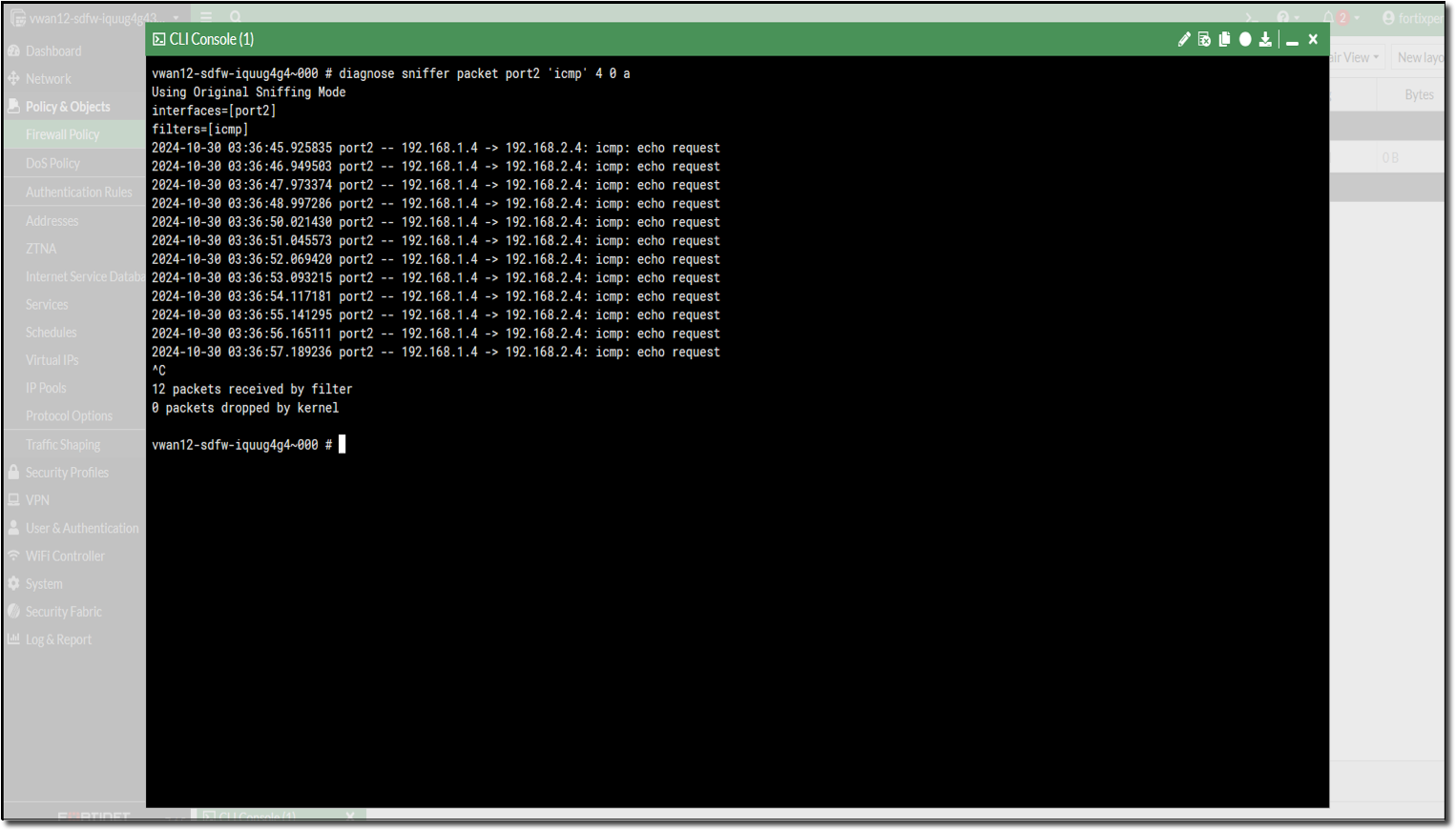
View ping traffic from Spoke VMs reaching the FortiGates
Open each FortiGate in a browser tab/window
Open FortiGate CLI
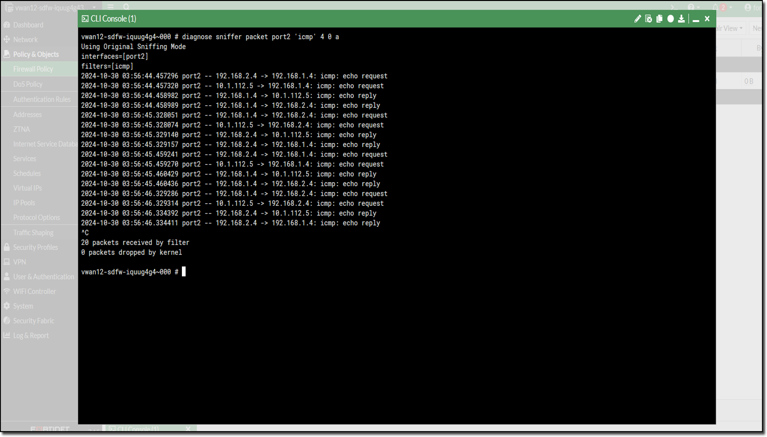
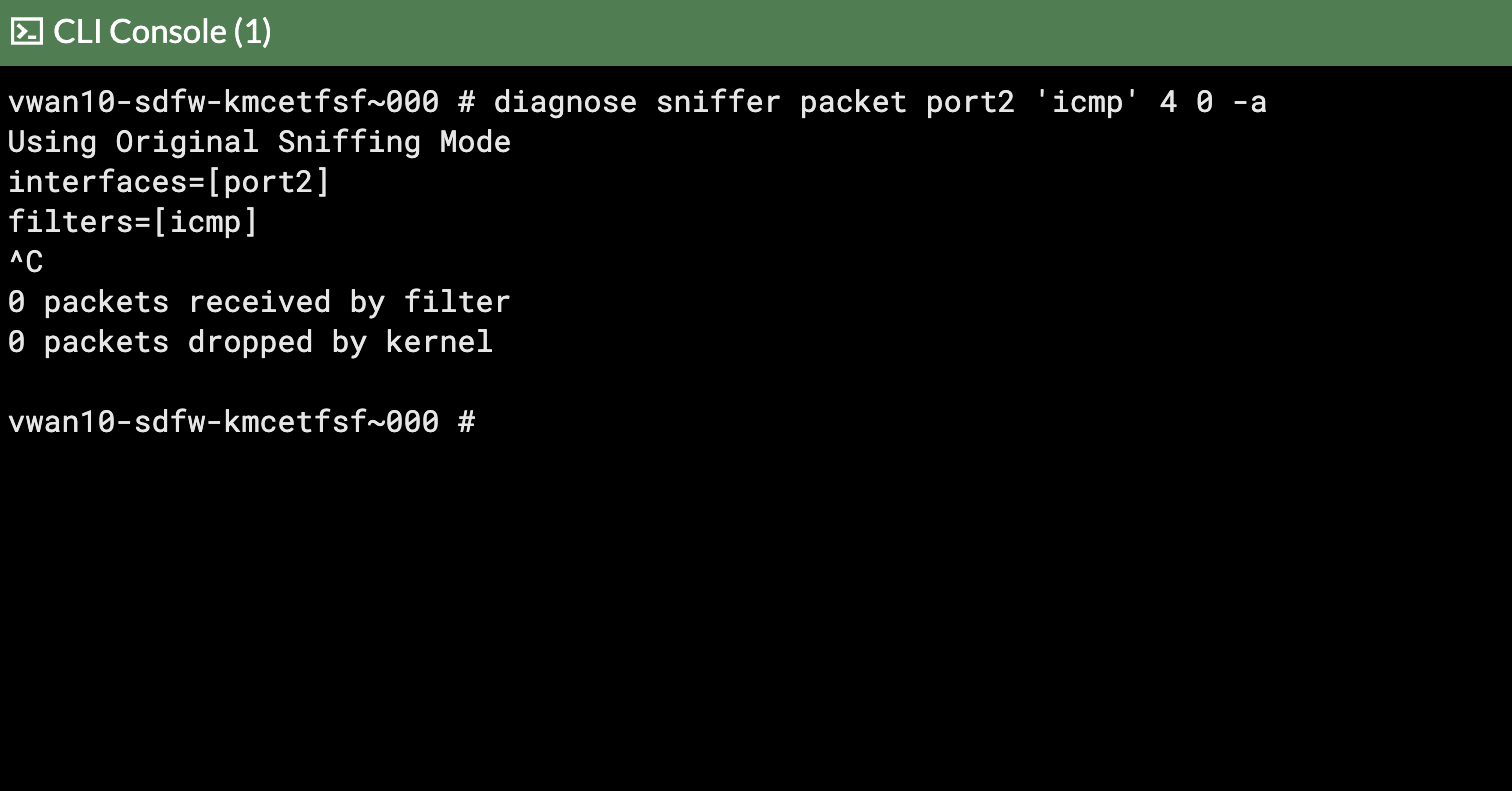
Run CLI command diagnose sniffer packet port2 'icmp' 4 0 a
4 - means: print header of packets with interface name
0 - means: continuous output
a - means: absolute UTC time, yyyy-mm-dd hh:mm:ss.ms
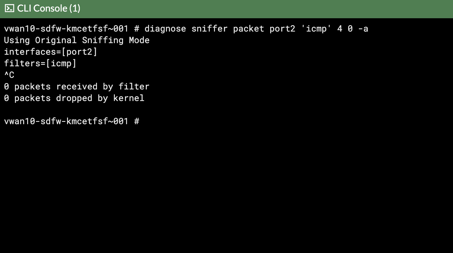
FortiGate 0
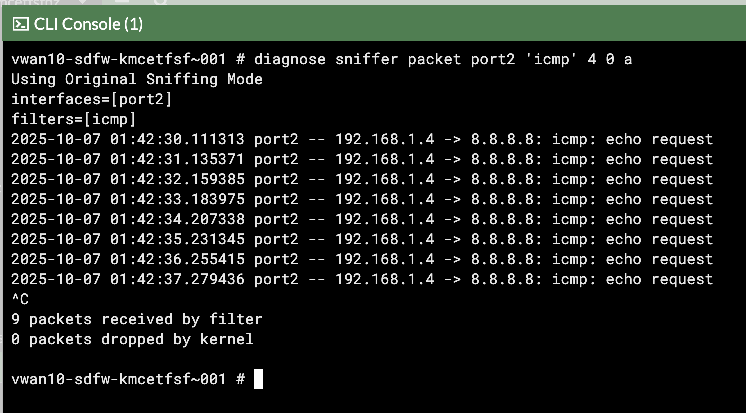
FortiGate 1
The ping traffic is only on one FortiGate, this is because the internal load balancer sends traffic from the Spokes to one of the FortiGates for inspection.
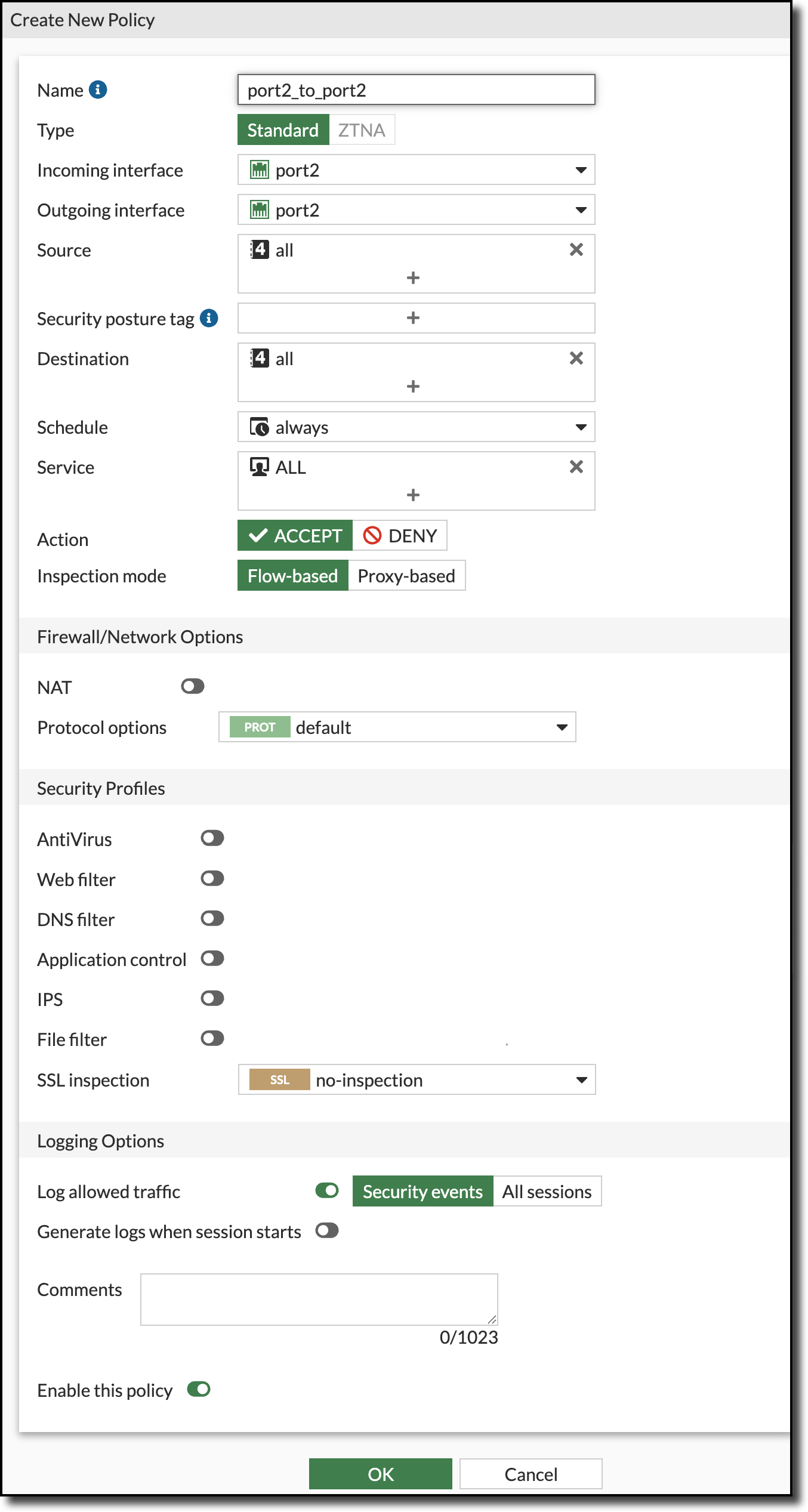
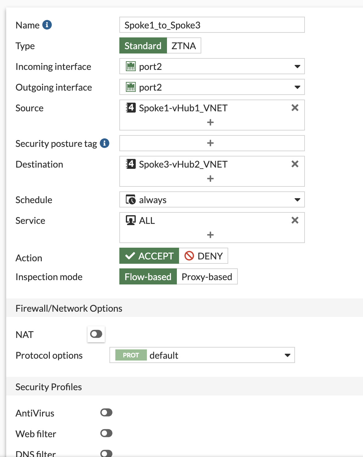
Create Firewall policies on both FortiGates to allow traffic to pass from port2 to port2 (Spoke to Spoke)
NOTE: The FortiGates can be setup to sync configuration information. If one of the FortiGates was designated as the primary configuration supplier and the other as a secondary, any changes made to the primary would be replicated to the secondary.
Configuration Synchronization was not enabled on the FortiGates as part of this course.
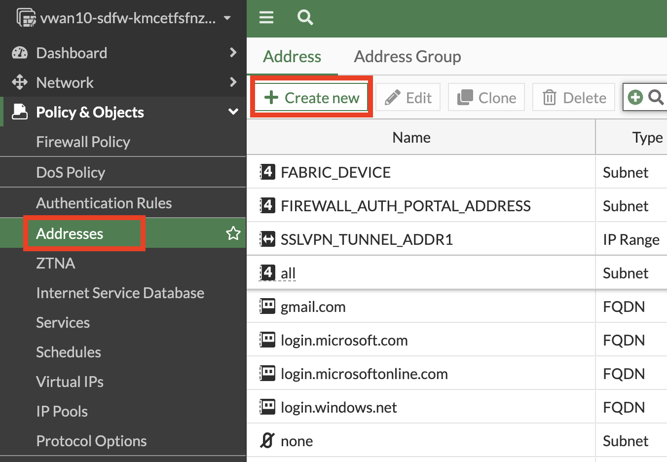
Navigate to “Policy & Objects”
Click Firewall Policy
Click Create new
Attribute
Value
Name
port2_to_port2
Incoming interface
port2
Outgoing interface
port2
Source
all
Destination
all
Schedule
always
Service
ALL
NAT
disabled
Enable this policy
enabled
Click “OK”
Ping between Linux Spoke VMs and confirm connectivity.
Linux-Spoke1-VM - ping 192.168.2.4
Linux-Spoke2-VM - ping 192.168.1.4
Linux-Spoke1-VM
Linux-Spoke2-VM
FortiGate 0
FortiGate 1
Continue to Chapter 5 - Task 2: North-South Network Traffic
Task 2: North-South Network Traffic
In this task create FortiGate firewall policies to allow North-South (Spoke to Internet) network traffic.
Ping from the Linux Spoke VMs to the Internet
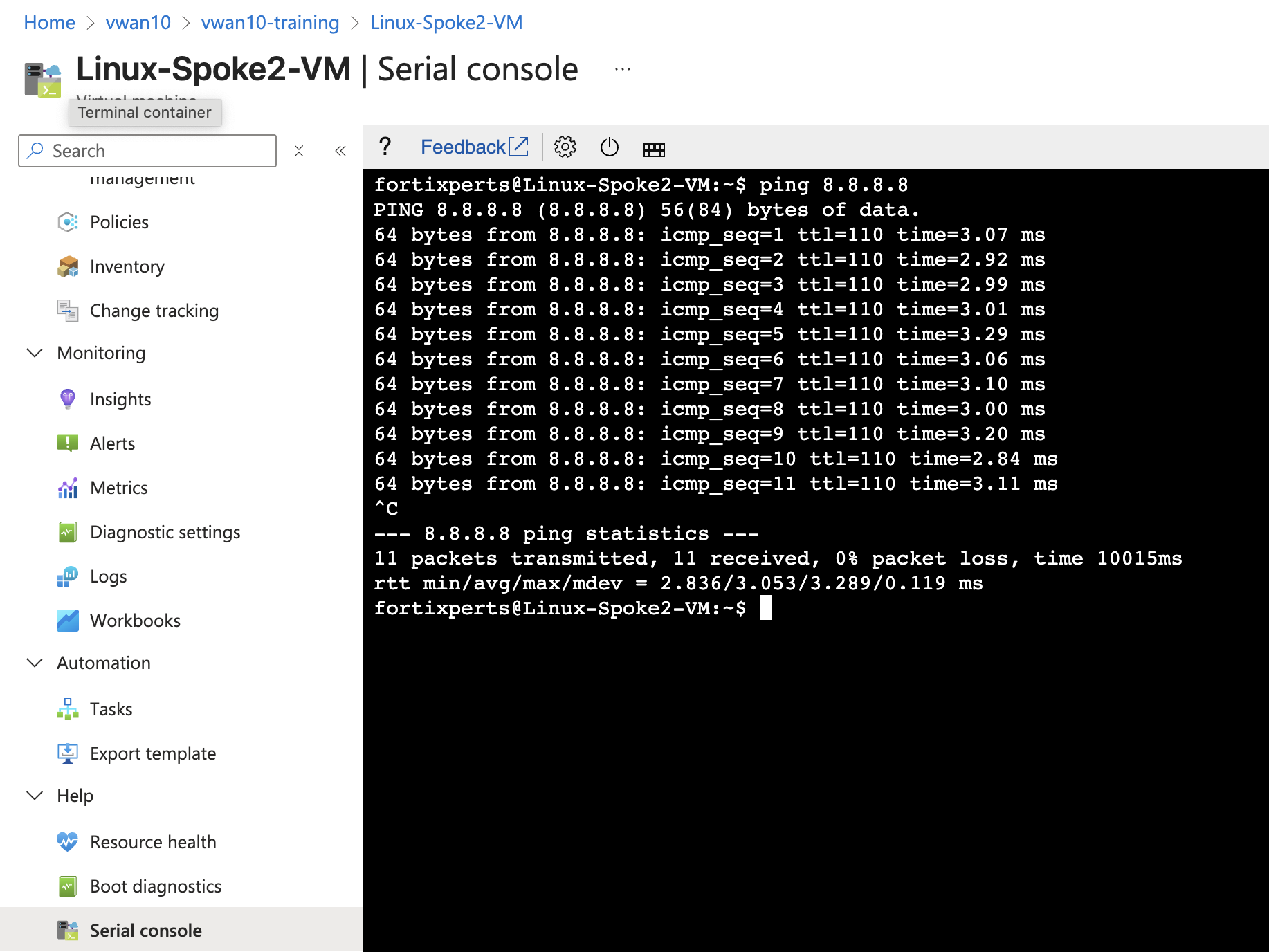
Open a serial console connections to each Linux Spoke VM and ping 8.8.8.8
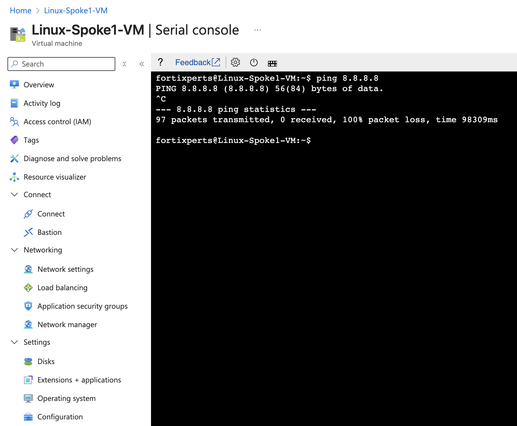
Linux-Spoke1-VM - ping 8.8.8.8
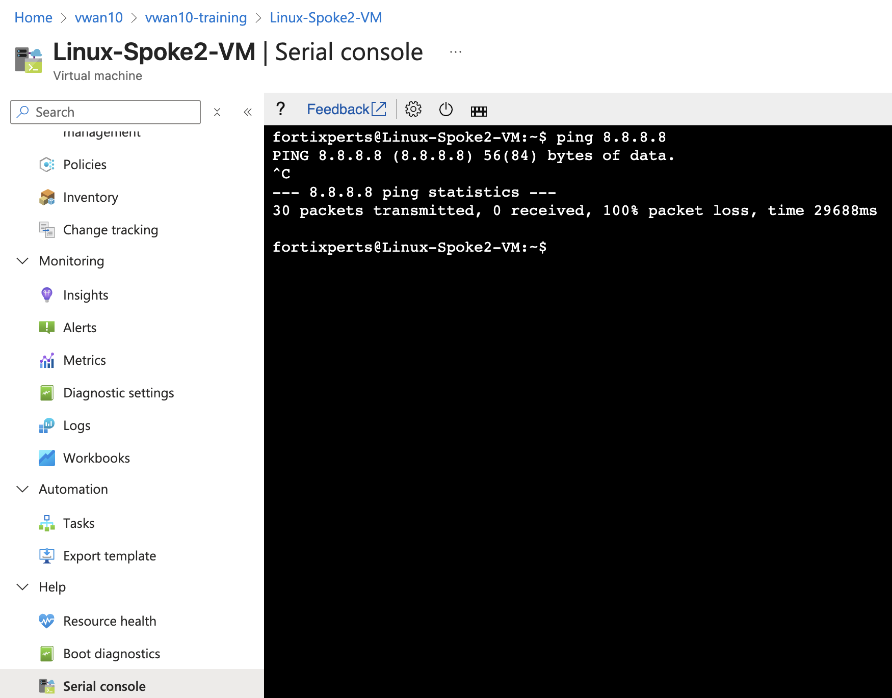
Linux-Spoke2-VM - ping 8.8.8.8
Also try wget https://www.fortinet.com
Neither ping nor wget will be successful because the FortiGate is not allowing traffic from port2 to port1.
Linux-Spoke1-VM
Linux-Spoke2-VM
However, the traffic from each VM does reach the FortiGate, but it is dropped. Firewall Policies are required to allow traffic to pass from port2 to port1, and then return back to the VM that originated the ping.
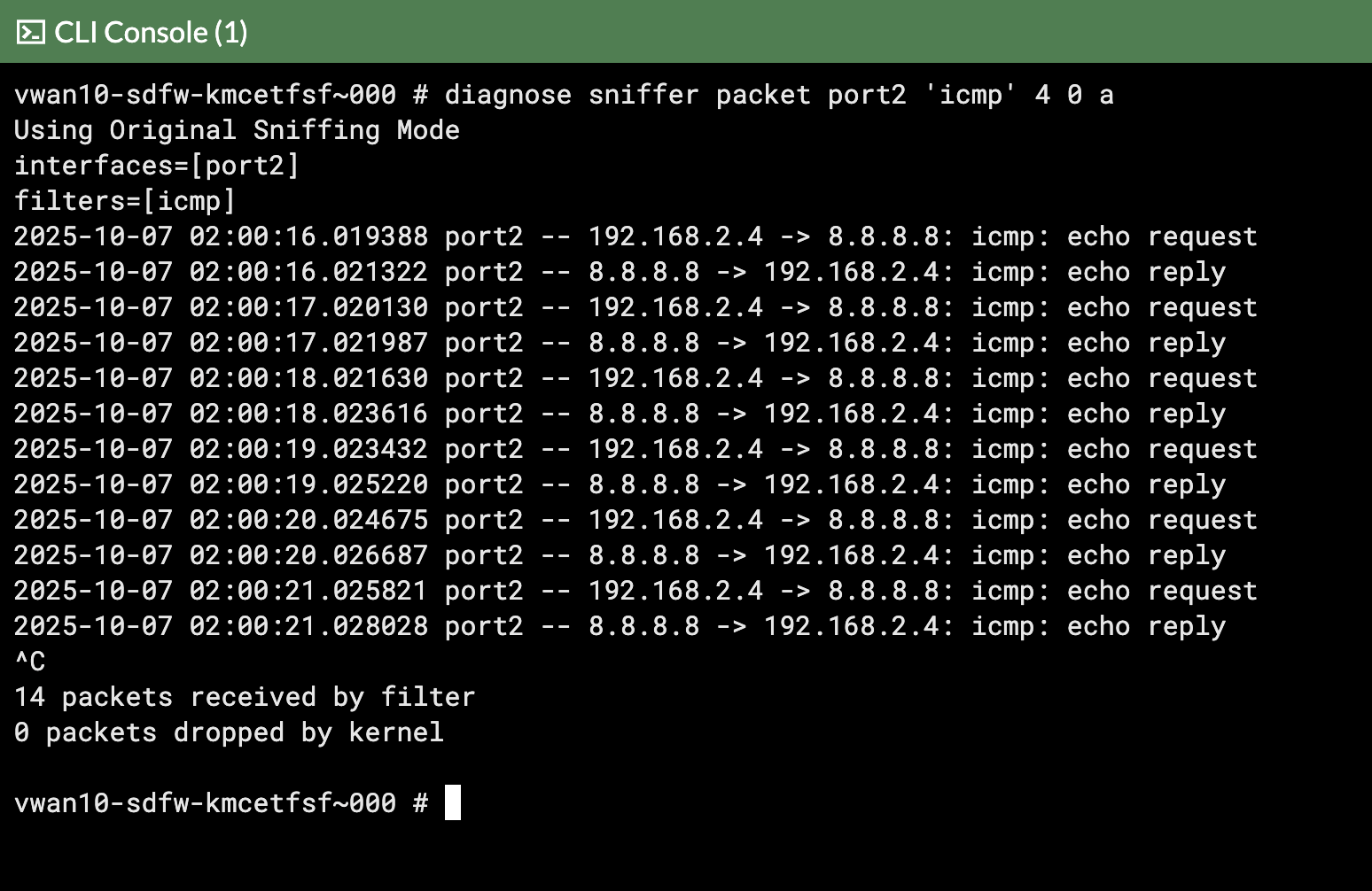
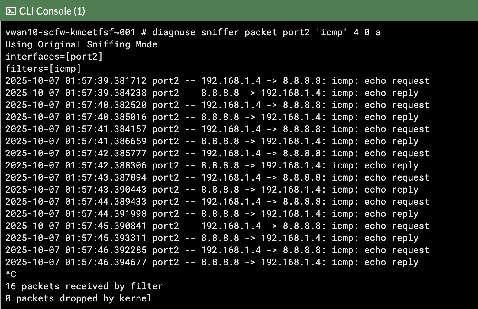
View ping traffic from Spoke VMs reaching the FortiGates
Open each FortiGate in a browser tab/window
Open FortiGate CLI
Run CLI command diagnose sniffer packet port2 'icmp' 4 0 a
4 - means: print header of packets with interface name
0 - means: continuous output
a - means: absolute UTC time, yyyy-mm-dd hh:mm:ss.ms
In the screenshots notice how this time the ping traffic appeared on FortiGate 1
FortiGate 0
FortiGate 1
The ping traffic is only on one FortiGate, this is because the internal load balancer sends traffic from the Spokes to one of the FortiGates for inspection.
View wget traffic with this FortiGate CLI
diagnose sniffer packet port2 'host www.fortinet.com' 4 0 a
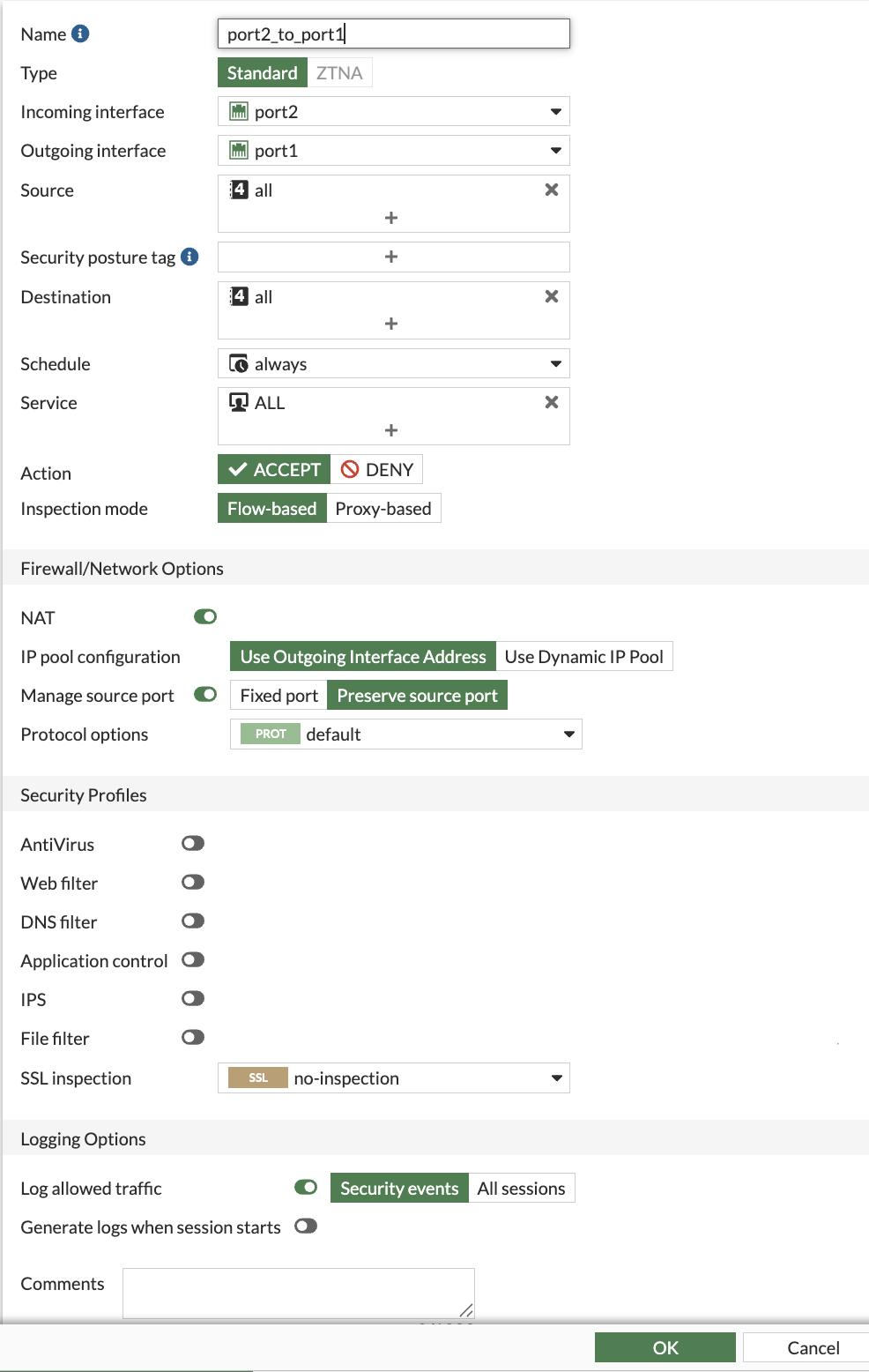
Create Firewall policies on both FortiGates to allow traffic to pass from port2 to port1 (Spoke to Internet)
The FortiGates can be setup to sync configuration information. If one of the FortiGates was designated as the primary configuration supplier and the other as a secondary, any changes made to the primary would be replicated to the secondary.
Configuration Synchronization was not enabled on the FortiGates as part of this course.
Navigate to “Policy & Objects”
Click Firewall Policy
Click Create new
Attribute
Value
Name
port2_to_port1
Incoming interface
port2
Outgoing interface
port1
Source
all
Destination
all
Schedule
always
Service
ALL
NAT
enabled
IP pool configuration
Use Outgoing Interface Address
Enable this policy
enabled
Click “OK”
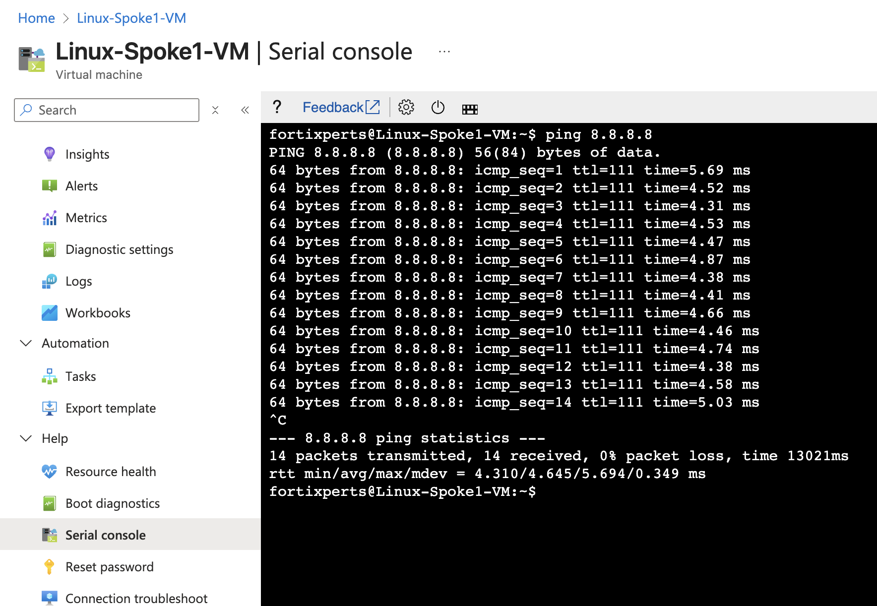
Ping from the Linux Spoke VMs to the Internet and confirm the pings are successful
Linux-Spoke1-VM - ping 8.8.8.8
Linux-Spoke2-VM - ping 8.8.8.8
Linux-Spoke1-VM
Linux-Spoke2-VM
FortiGate 0
FortiGate 1
Continue to Chapter 5 - Task 3: Internet Inbound
Task 3: Internet inbound Traffic
In this task create FortiGate firewall policies and DNAT (Destination Network Address Translation) policies on the Load balancer to allow Internet inbound network traffic.
Find Internet Inbound IP Address
From your assigned Resource Group “vwanxx-training”, navigate to your vWAN “vwanxx-training_VWAN” and then your hub “vwanXX-eastus-vHub1_VHUB”
Click Network Virtual Appliance in the left-hand navigation
Click on “Manage Configurations” in the right-hand “Network Virtual Appliances” pane
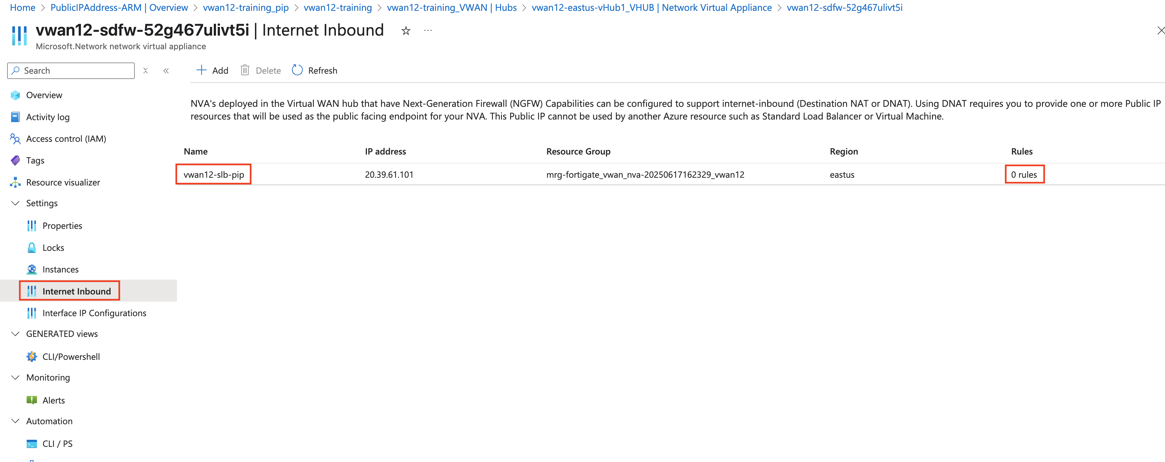
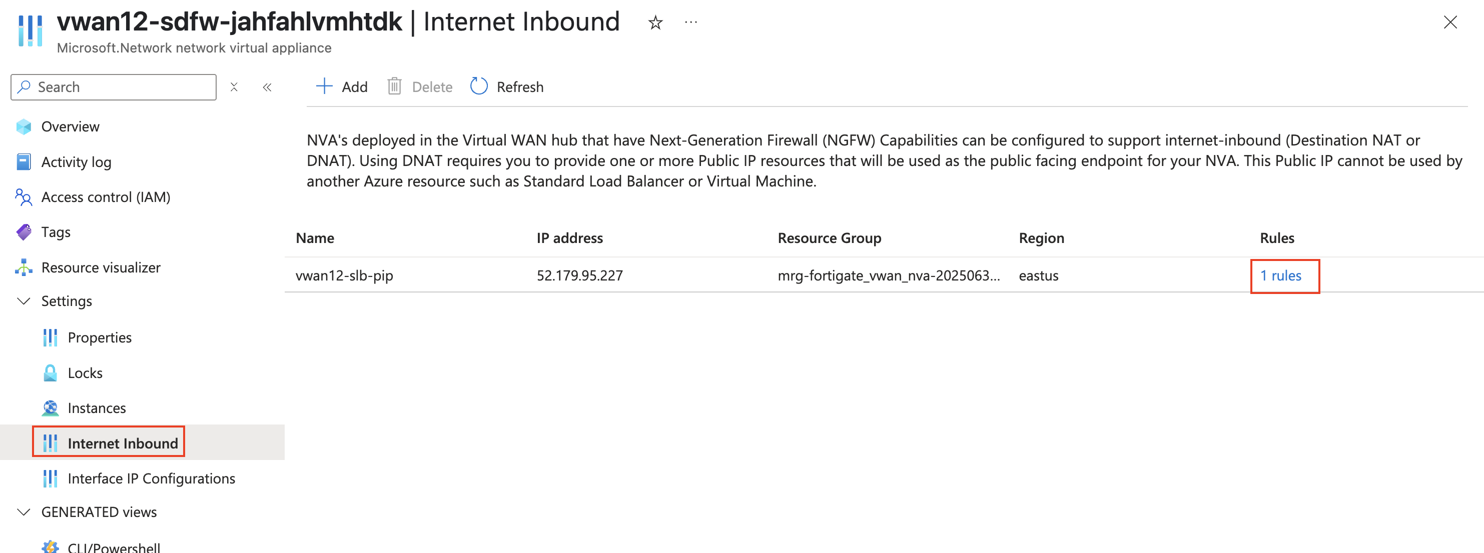
Click on Internet Inbound in the left-hand navigation
Note You should see a Public IP with “vwanxx-slb-pip” assigned to the load balancer. Notice there are 0 rules assigned to the Loadbalancer
Load Balancer Rules are required to allow traffic inbound. Each rule specifies IP, Port, and Protocol
Copy the Name (vwanxx-slb-pip) and IP address to a notepad
To access the CLI on your FortiGate NVAs, following these steps:
From your assigned Resource Group “vwanxx-training”, navigate to your vWAN “vwanxx-training_VWAN” and then your hub “vwanXX-eastus-vHub1_VHUB”
Click Network Virtual Appliance in the left-hand navigation
Click “Click here” link under “Instances info” in the right-hand “Network Virtual Appliances” pane
Note FortiGate Public IP and Private IP addresses
Open a browser tab to each FortiGate using the Public IP address of each FortiGate
Login to the Fortigate with _0 suffix by using the Public IP address with the provided credentials. Example: vwanxx-sdfw-52g467ulivt5i_0
Click on the >_ at the top right corner.
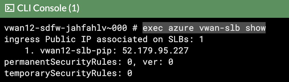
Copy this command exec azure vwan-slb show
Note Should see output like below
Click on the >_ at the top right corner.
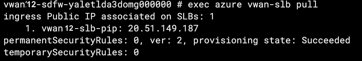
Copy this command exec azure vwan-slb pull
Note Should see output like below
Copy the below configuration to create rules on the loadbalancer.
Warning
Load Balancer rules only need to be configured on one FortiGate NVA.
Warning
Make sure to change the applies-on to reflect the name of your Public IPCopy these CLI commands to notepad or similar tool to update the vwanxx-slb-pip, if required.
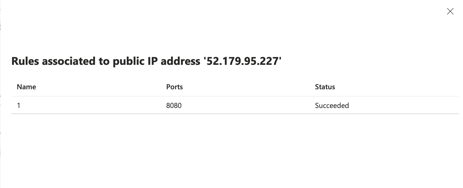
Click Rules to show the rules associated with Public IP address.
Login to both the NVA FortiGate’s again to create a VIP to the web Server on both FortiGates.
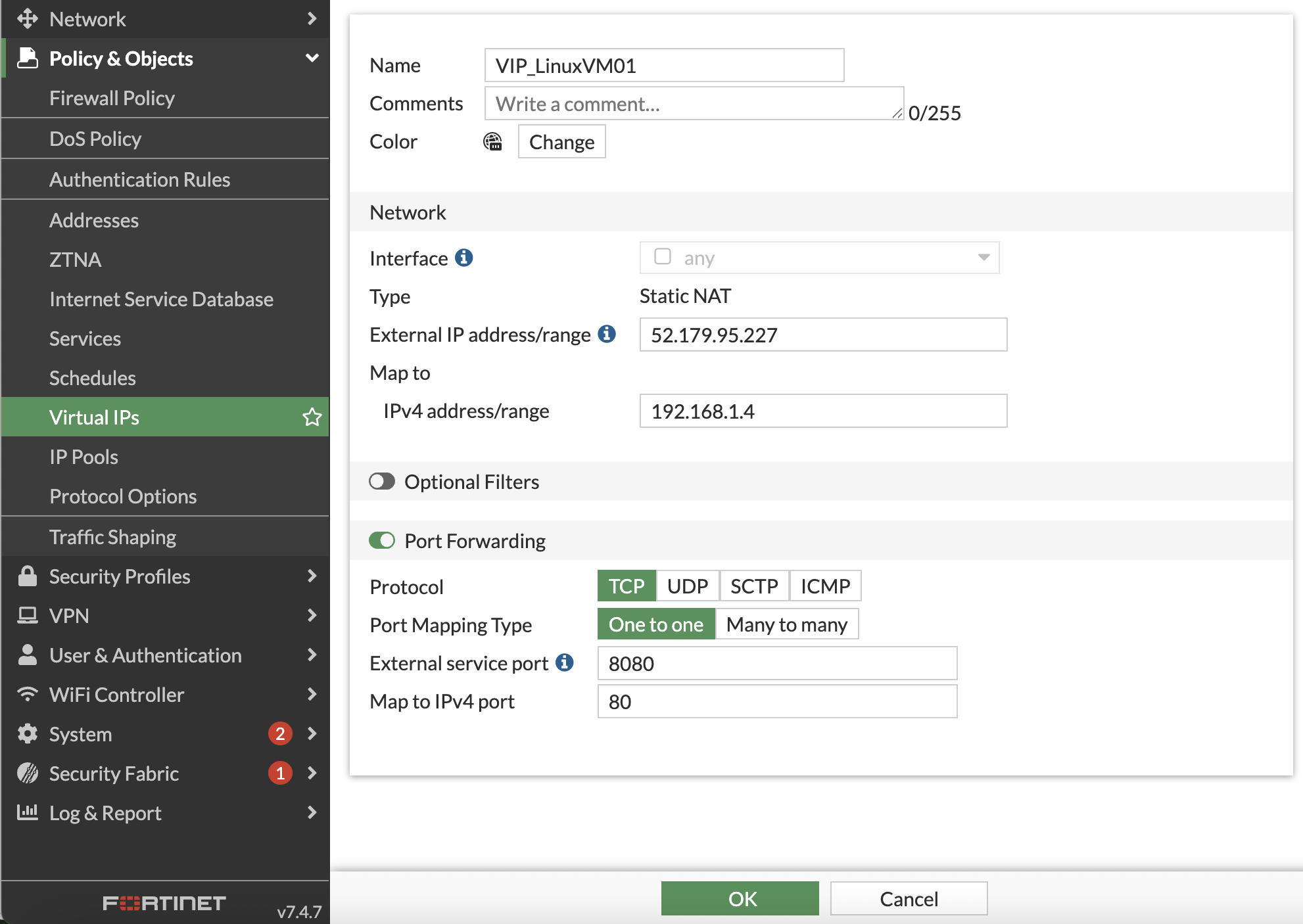
Navigate to Policy & objects > Virtual IP’s
Create a new VIP with the following.
Attribute
Value
Name
VIP_LinuxVM01
Interface
any
External IP address/range
Use IP address of Loadbalancer named vwanxx-slb-pip
Map to IPv4 address/range
192.168.1.4
Port forwarding
enabled
Protocol
TCP
Port Mapping Type
one to one
External service port
8080
Map to IPv4 port
80
Click “OK”
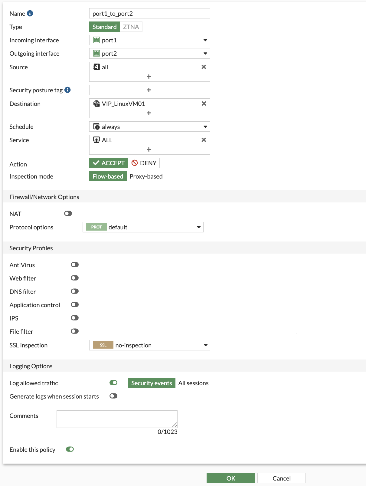
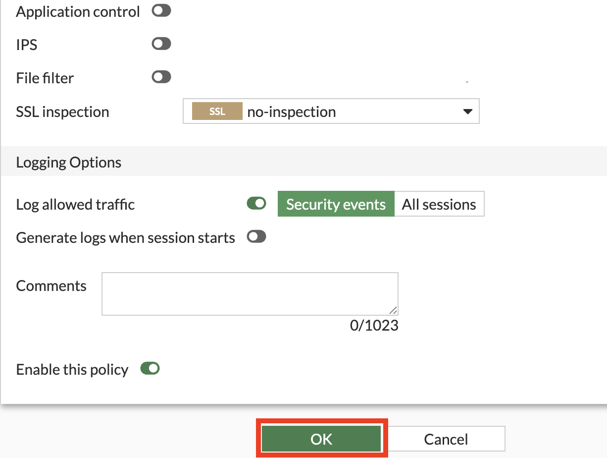
Create Firewall policies on both FortiGates to allow traffic to pass from port1 to port2 (Internet to Spoke)
The FortiGates can be setup to sync configuration information. If one of the FortiGates was designated as the primary configuration supplier and the other as a secondary, any changes made to the primary would be replicated to the secondary.
Configuration Synchronization was not enabled on the FortiGates as part of this course.
Navigate to “Policy & Objects”
Click Firewall Policy
Click Create new
Attribute
Value
Name
port1_to_port2
Incoming interface
port1
Outgoing interface
port2
Source
all
Destination
VIP_LinuxVM01
Schedule
always
Service
ALL
NAT
disabled
Enable this policy
enabled
Click “OK”
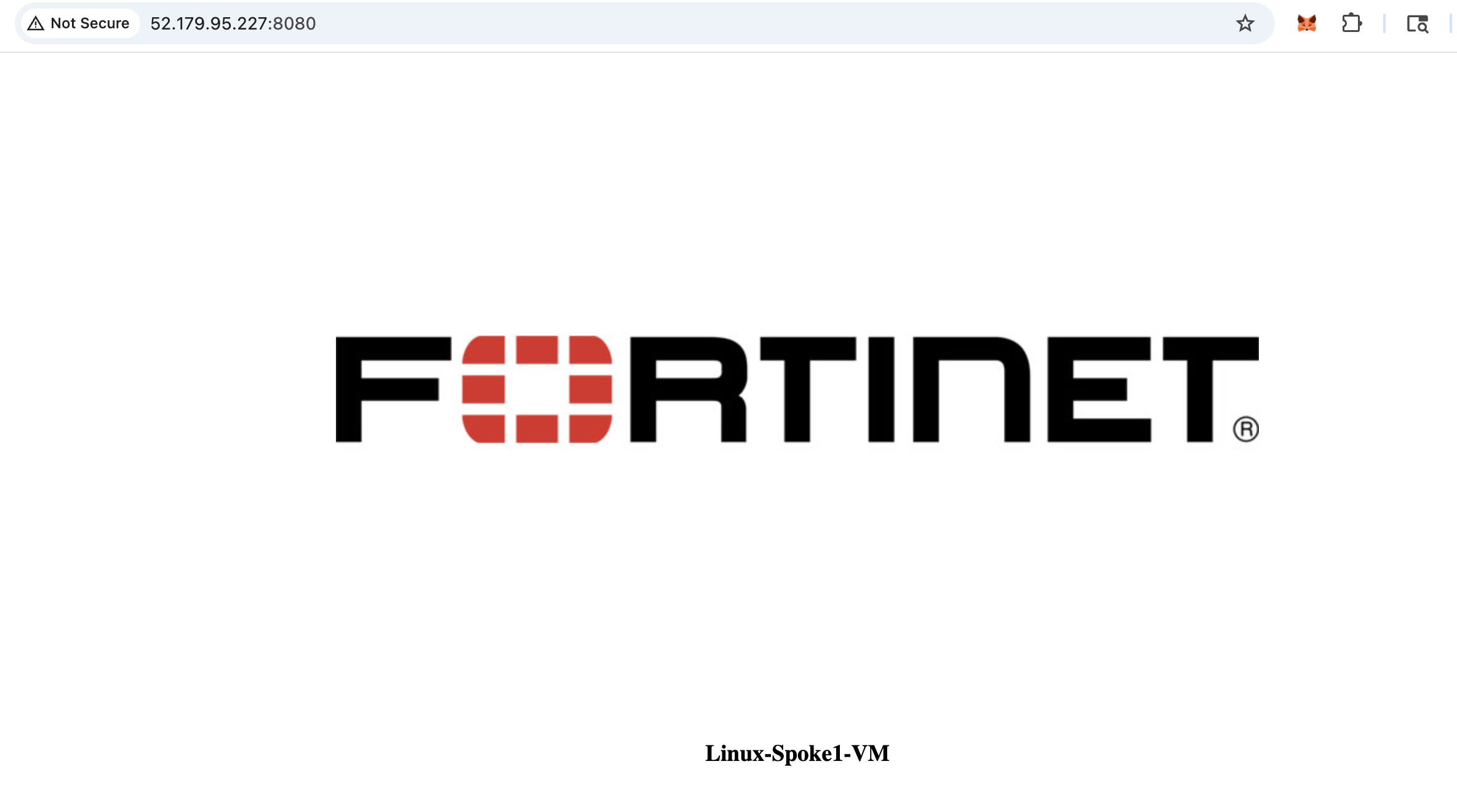
Navigate to a web browser and check if able to reach the web server with vwanxx-slb-pip IP that was used in creating the VIP and port 8080
http://vwanxx-slb-pip:8080
Continue to Chapter 6 - Two vWAN Hubs
Chapter 6: Two vWAN Hubs
Goal
Gain Experience with deploying a dual VWAN Hub in a different region
Task
Deploy VWAN Hub, Create an Azure VNET, Deploy Linux VM, Peer the VNET to VWAN Hub and verify connectivity.
Validation
Able to control and Route traffic between VNETs peered between two different Hubs
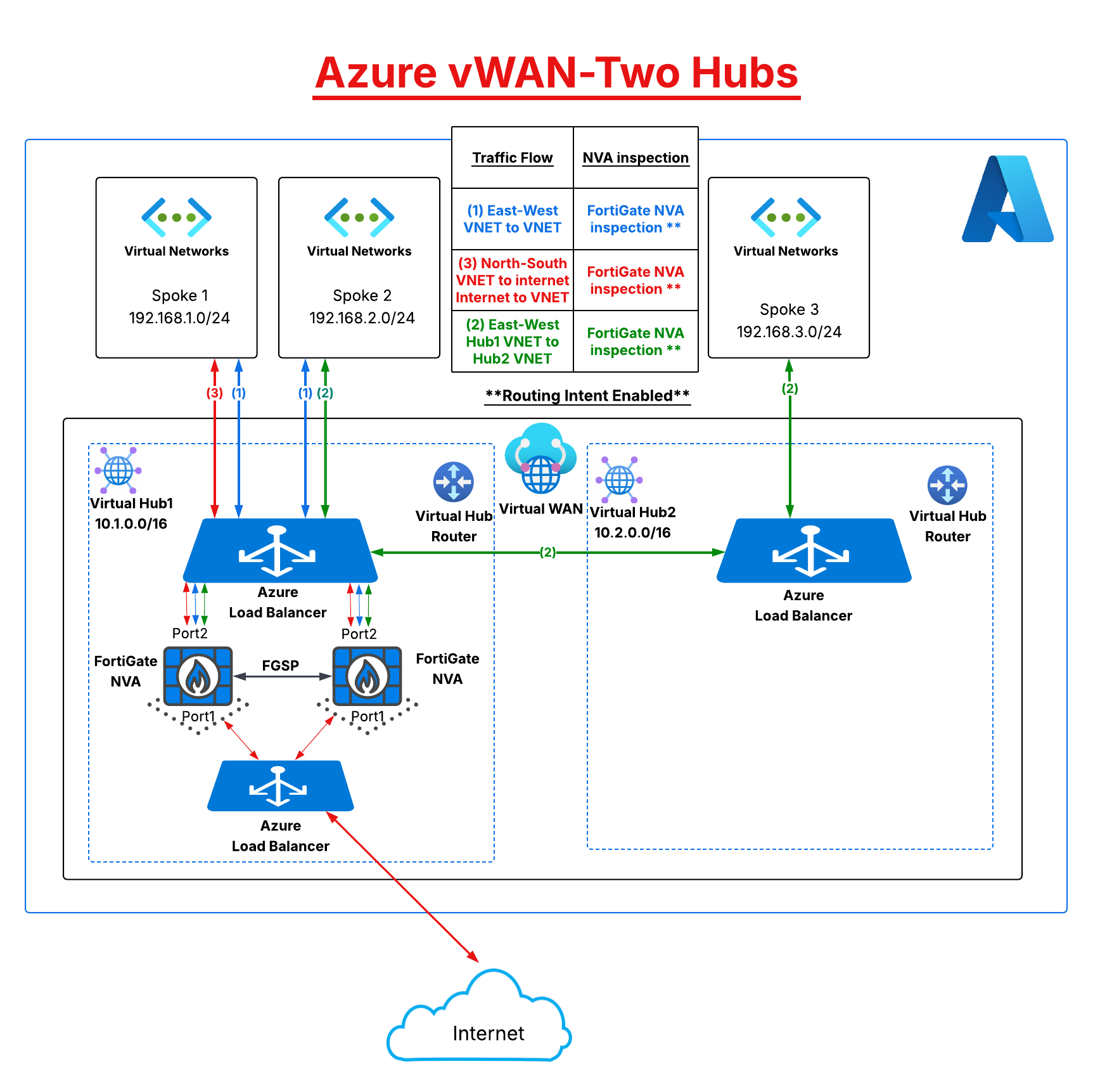
In chapter six deploy a second vWAN hub and create a VNET, peer the VNET to the new hub, deploy a Linux VM, and managed network connectivity between the two hubs.
Overview
Deploy a second vWAN hub in another Azure region
Create an Azure VNET
Deploy a Linux VM
Peer the new VNET to the second vWAN hub and verify route tables
Manage network traffic between the two hubs
After you have completed the above tasks, the diagram below is a visual representation of what you will have deployed and configured.
Continue to Chapter 6 - Task 1: Deploy a second VWAN Hub
Subsections of Chapter 6: Two vWAN Hubs
Task 1: Deploy a second VWAN Hub
In this task deploy a second vWAN hub.
Deploy a VWAN Hub
The initial vWAN hub setup was already done for you before the session. Now you will deploy a second hub in another Azure region. The hub will eventually have a Virtual Network (VNET) peered to it, with a Linux VM deployed in the VNET as well.
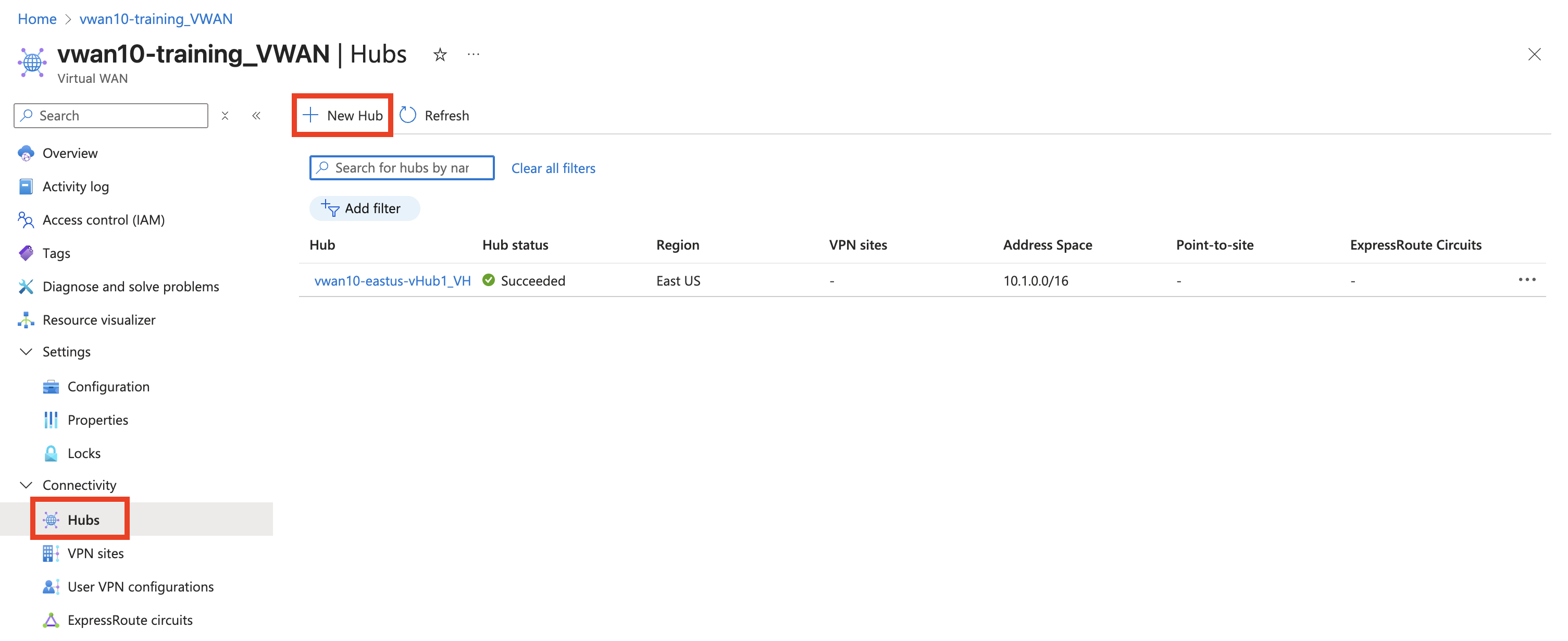
Add a VWAN Hub.
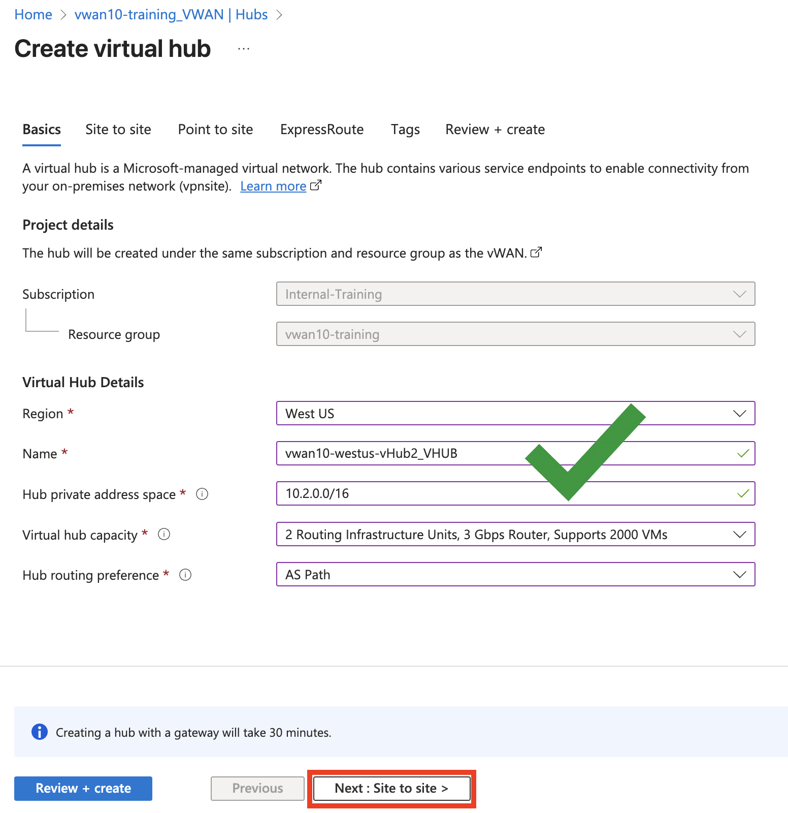
Navigate to your assigned vWAN vwanXX-eastus_VWAN
On the left under “Connectivity” select “Hubs”.
Click - “+ New Hub” button
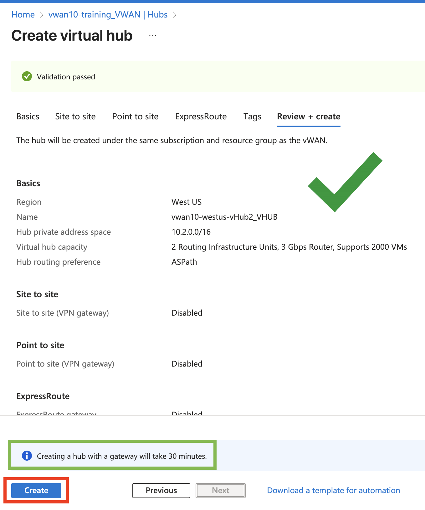
Select - Region “West US”
Enter - Name vwanXX-westus-vHub2_VHUB <– Where XX is your assigned number.
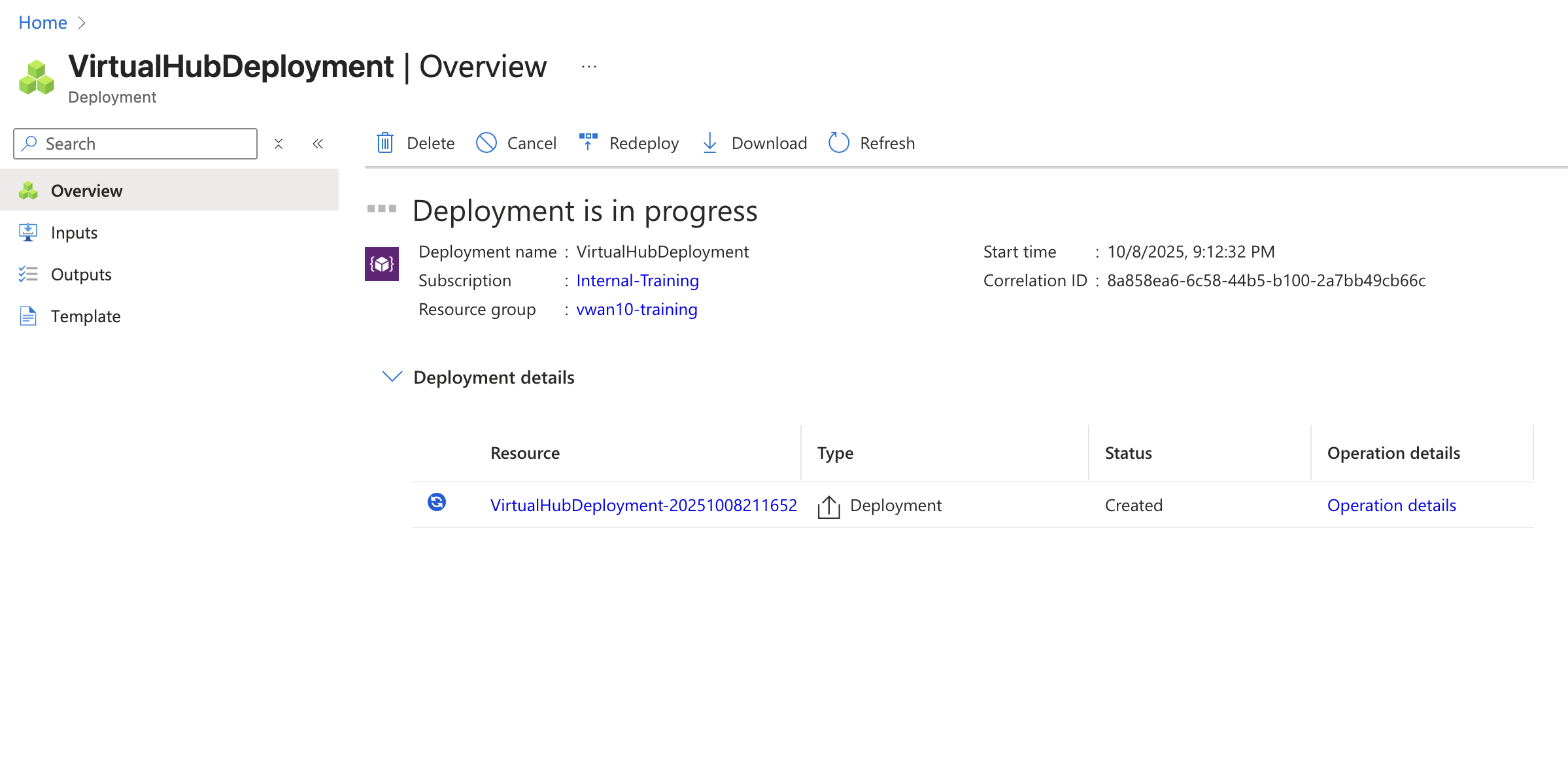
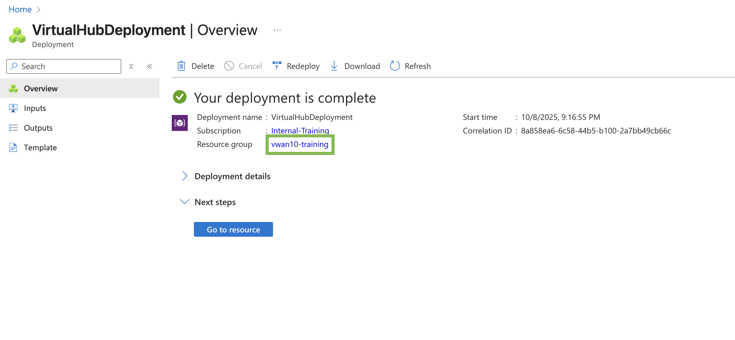
A deployment progress screen will be shown followed by a deployment completion screen. Hub deployment can take up to 30 minutes. Leave this browser tab open until you confirm the deployment has completed. Open the Azure portal in another browser tab and continue with the next task.
Continue to Chapter 6 - Task 2: Deploy a VNET
Task 2: Deploy a VNET
Deploy a VNET
Azure Virtual Networks (VNET) can be peered to a vWAN hub. Once a VNET is peered to a vWAN hub, workloads in the VNET can communicate with workloads in other VNETs connected to other vWAN hubs that are part of the same vWAN.
Add a VNET
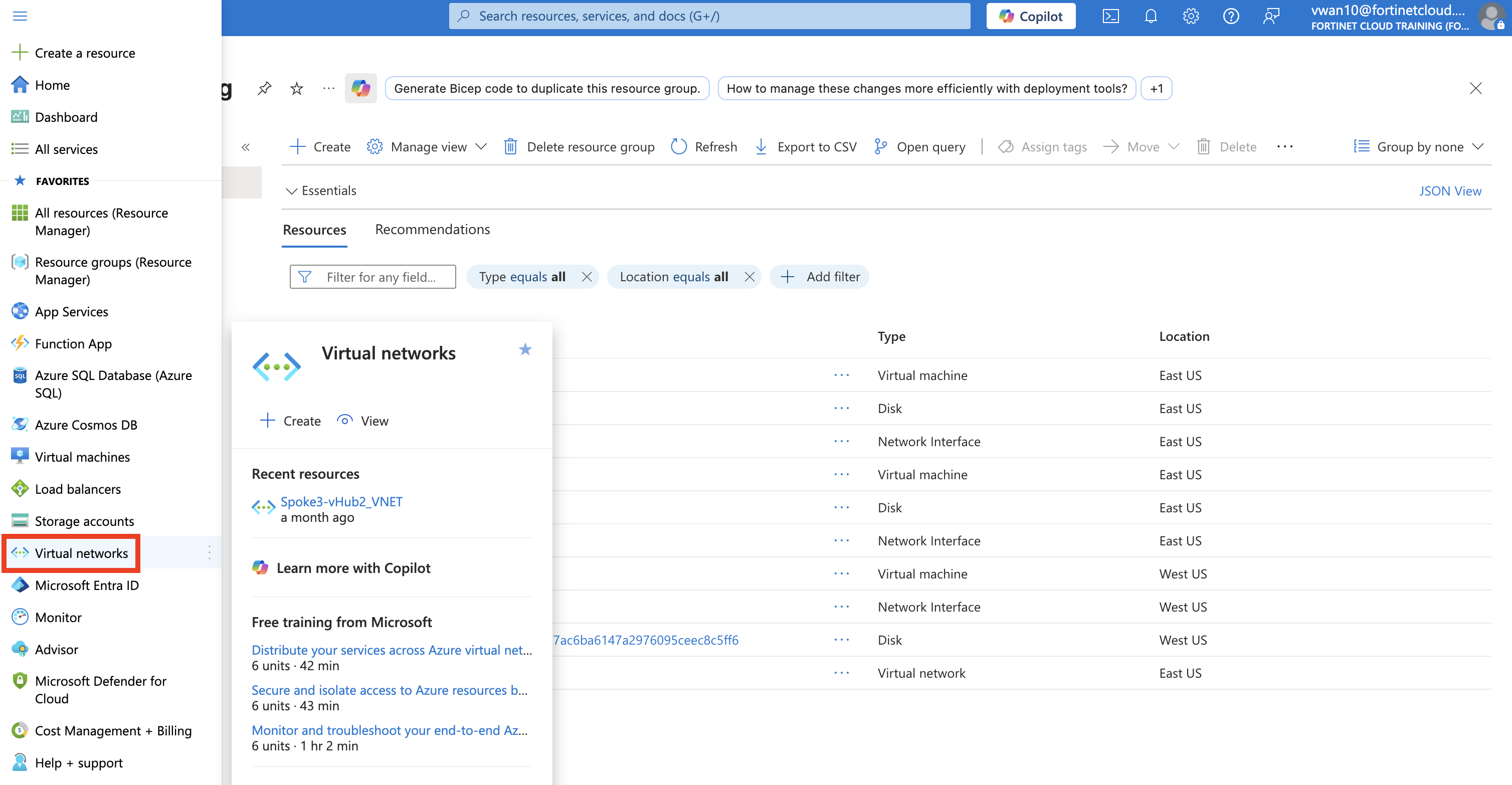
Navigate to your Resource Group vwanXX-training
Click - The Portal Menu button in the upper-left corner, sometime referred to as the hamburger button
Select - Virtual Networks in the left-hand navigation
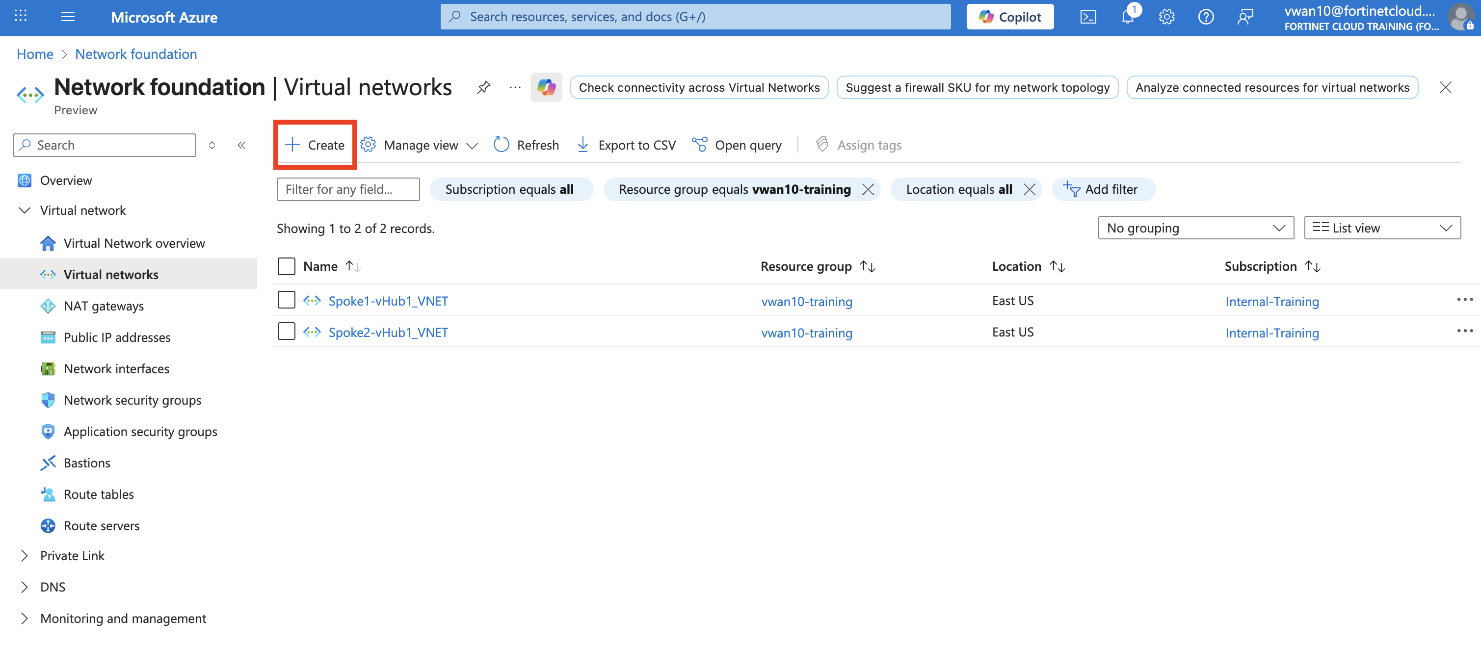
Click - “+ Create” button
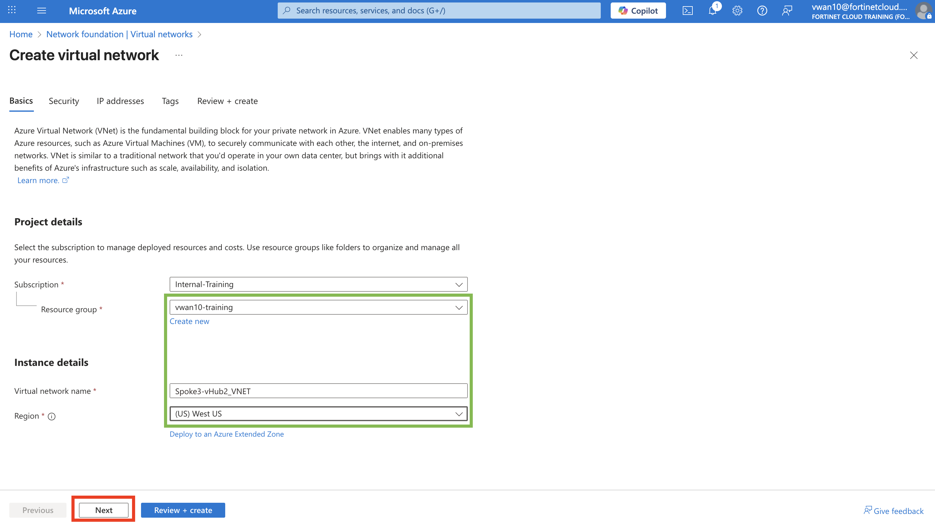
Select - your Resource Group vwanXX-training
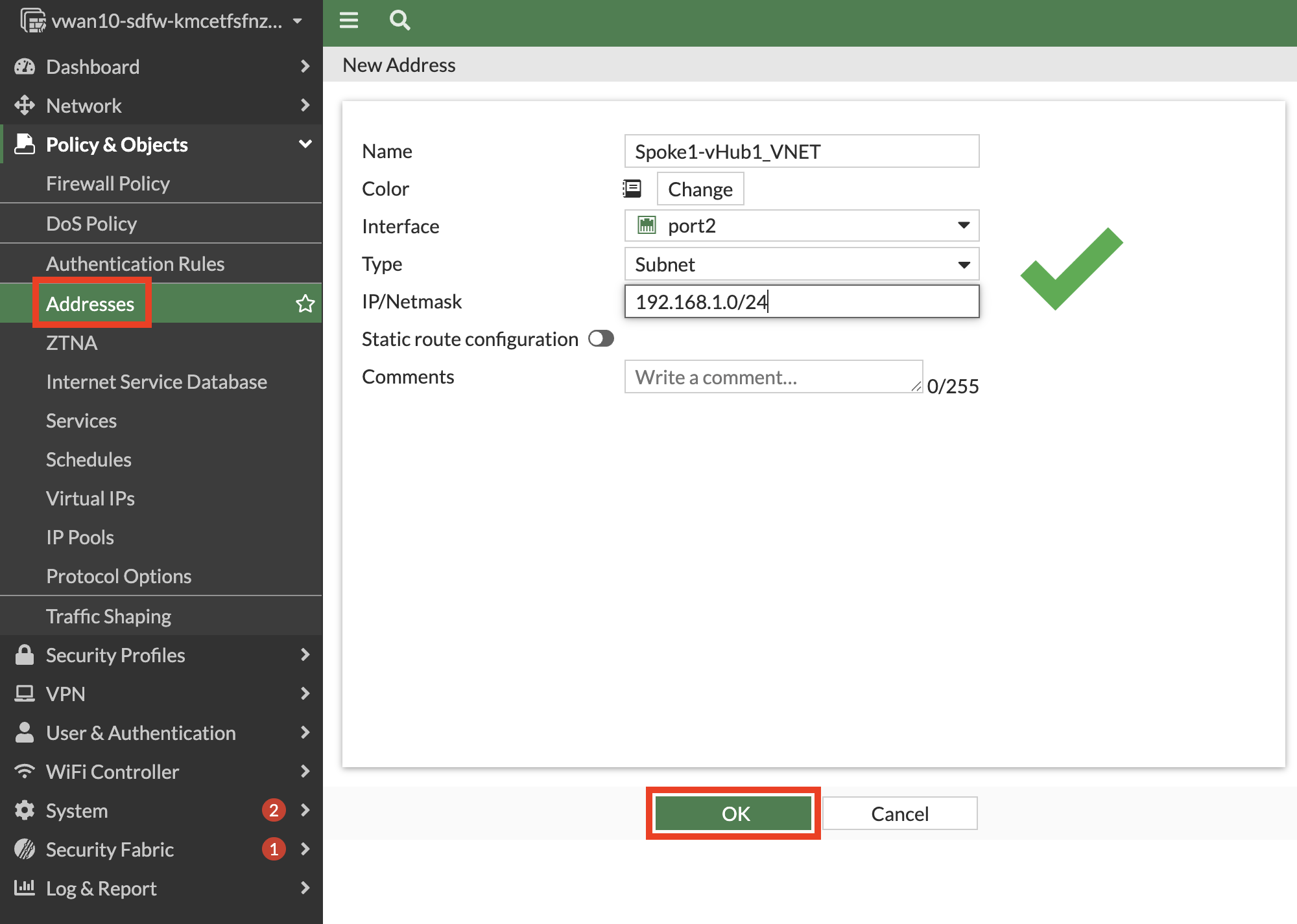
Enter - Virtual network name Spoke3-vHub2_VNET
Select - Region “(US) West US”
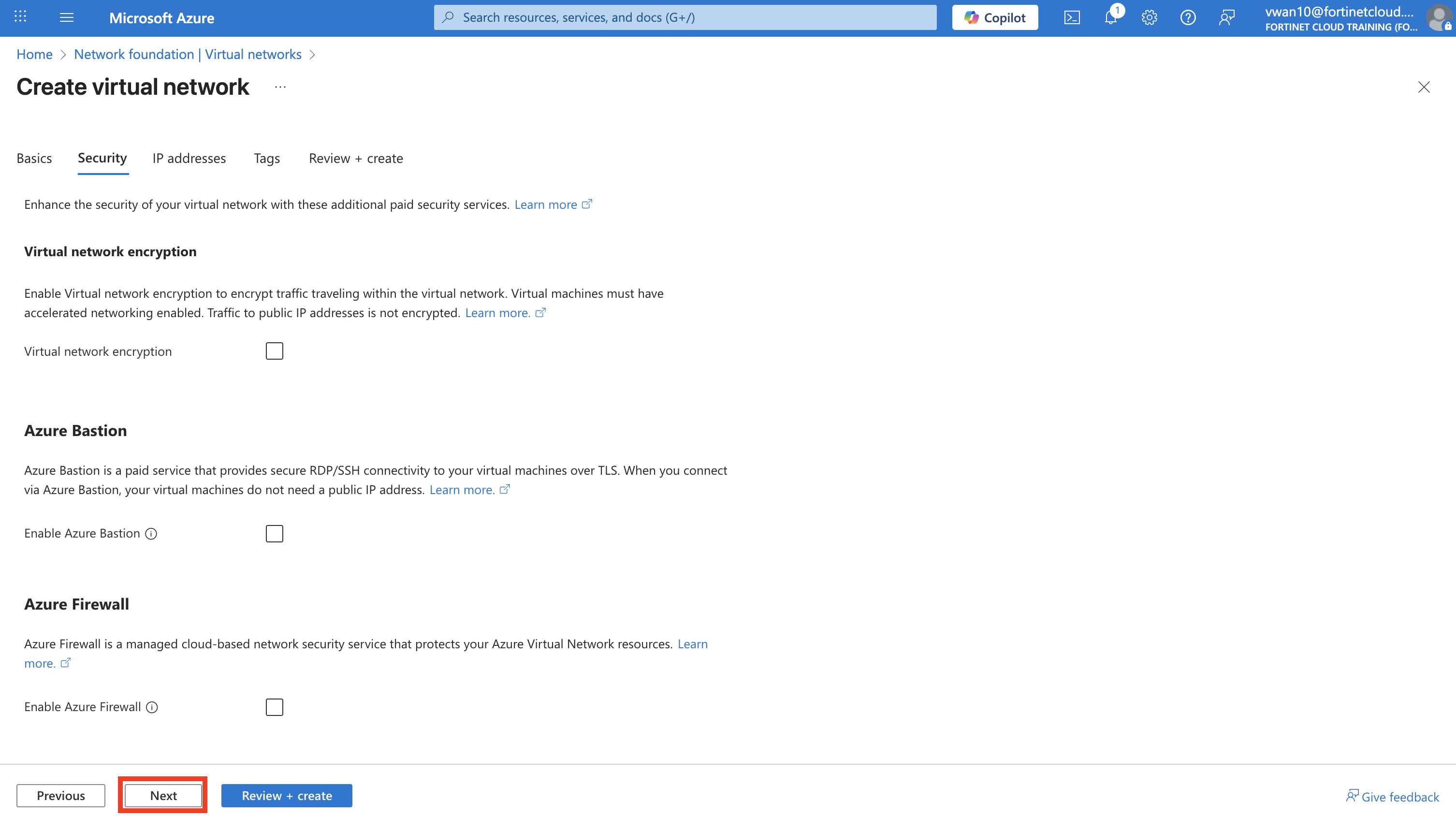
Click - “Next” button
Click - “Next : IP addresses” button on “Security” tab
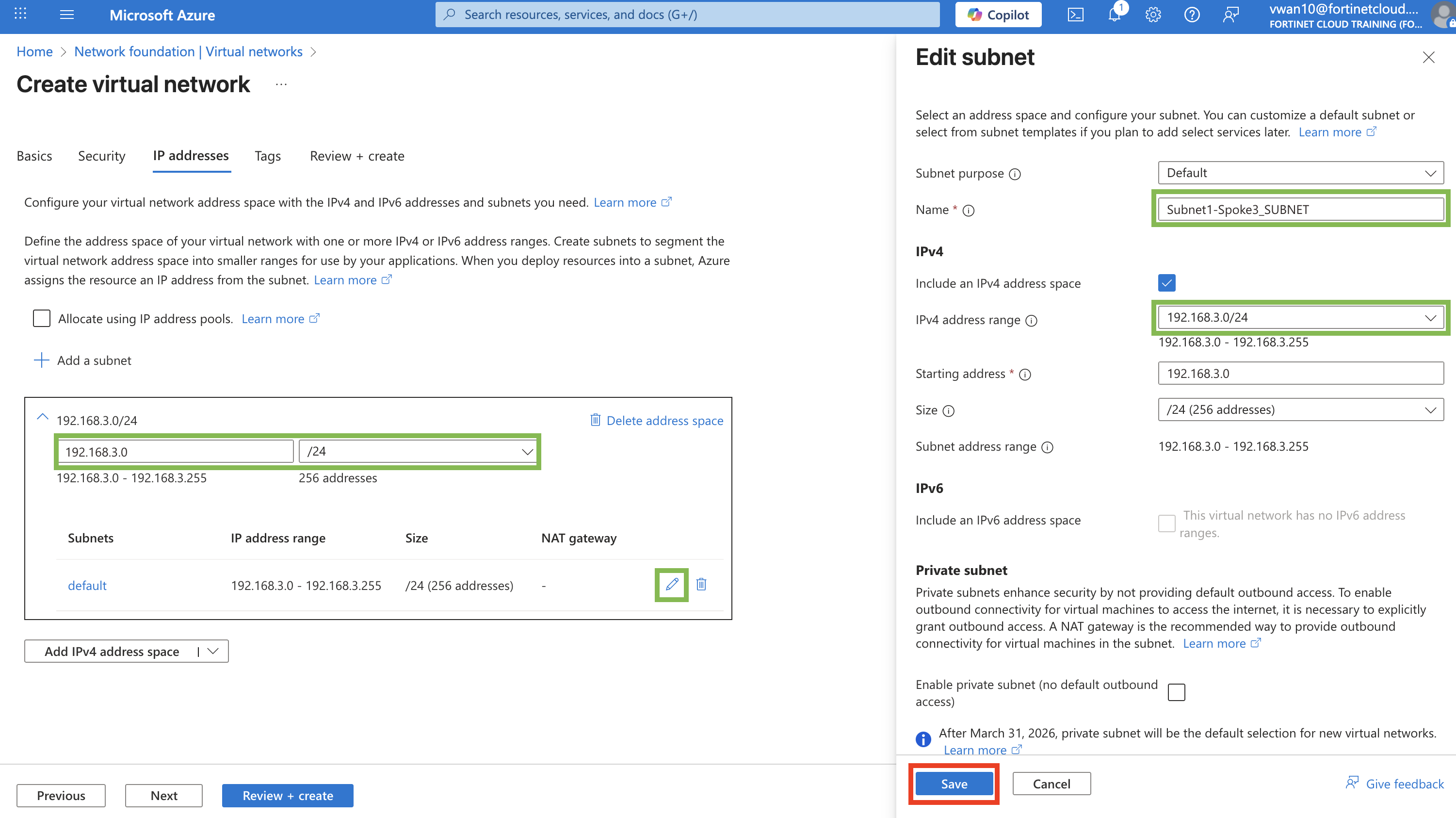
Enter - Address Space 192.168.3.0
Select - Netmask /24
Click - “Pencil” button to edit subnet configuration
Enter - Name Subnet1-Spoke3_SUBNET
Enter - Starting address 192.168.3.0
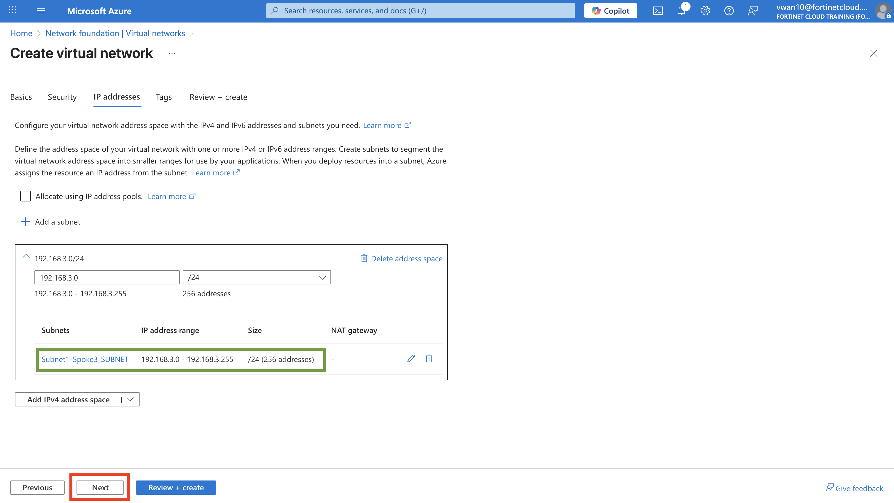
Click - “Save” button
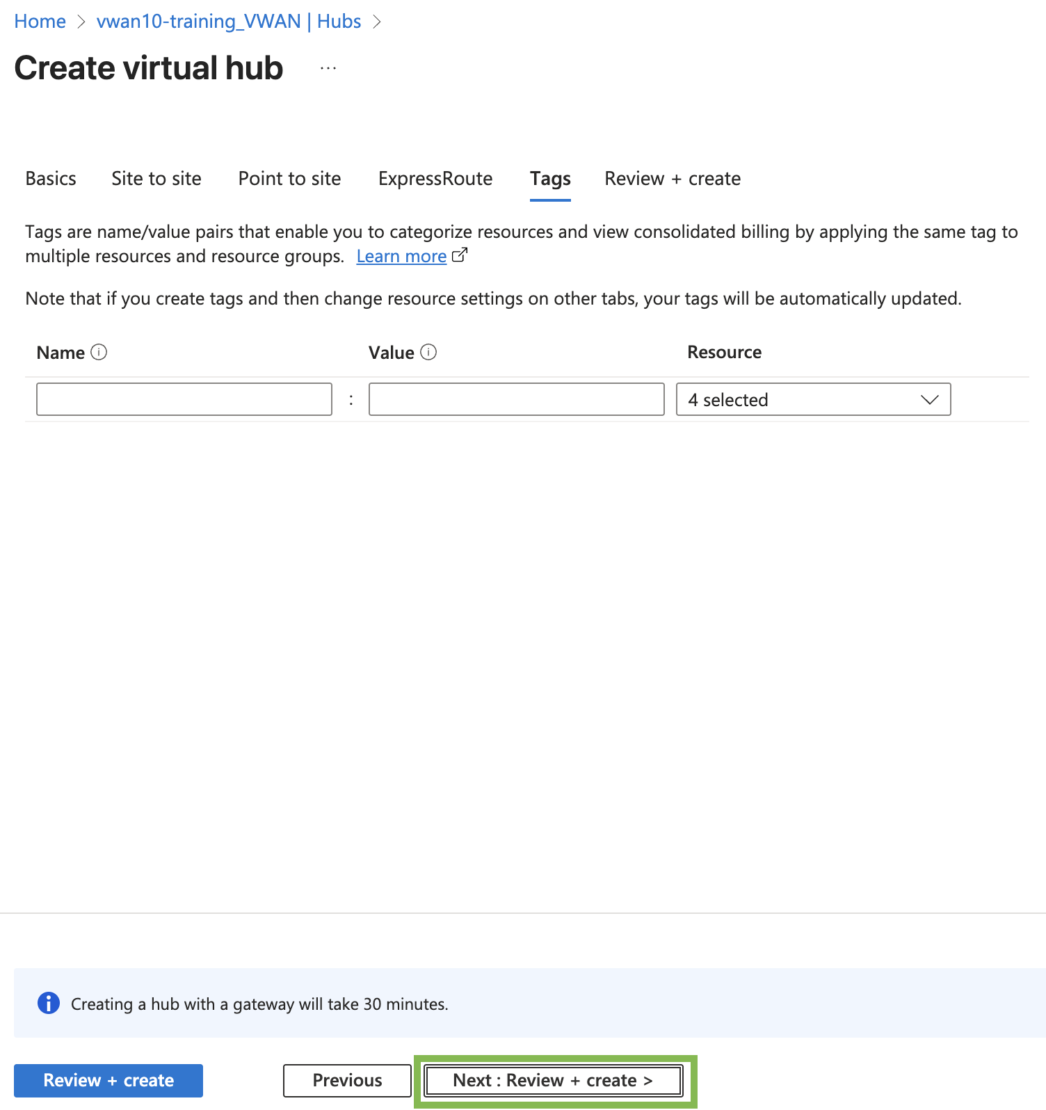
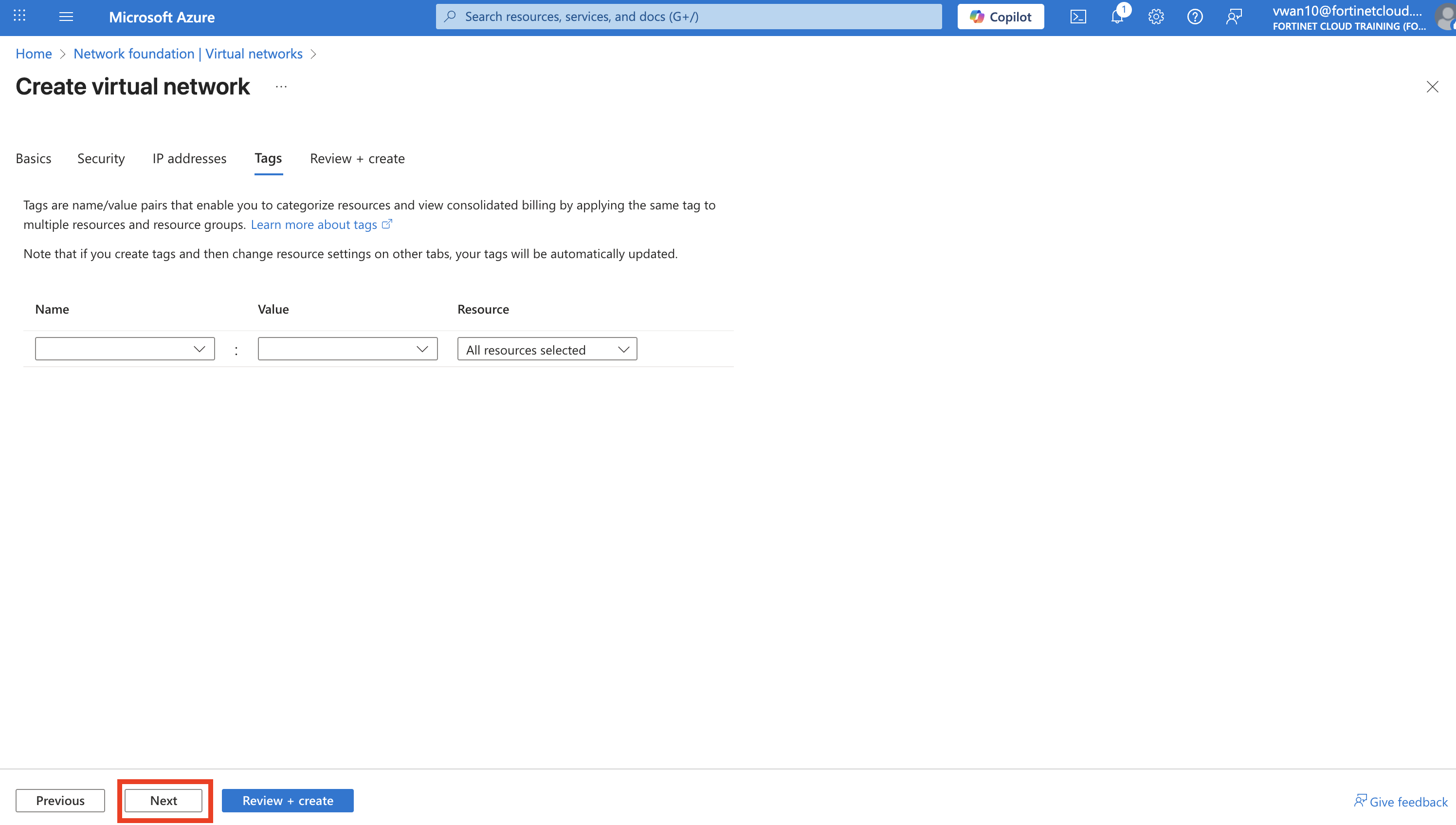
Click - “Next : Tags” button
Click - “Next : Review + create” button
Click - “Create” button
Click - your resource group name when the deployment is complete and confirm the new “Spoke3-vHUB2_VNET”.
Continue to Chapter 6 - Task 3: Deploy a Linux VM
Task 3: Deploy a Linux VM
Deploy a Linux VM
Now that the “Spoke3-vHub2_VNET” VNET is deployed, deploy a Linux VM in Spoke3-vHub2_VNET. This VM will be used to test hub to hub connectivity between spokes peered to different hubs.
Steps to create a Linux VM
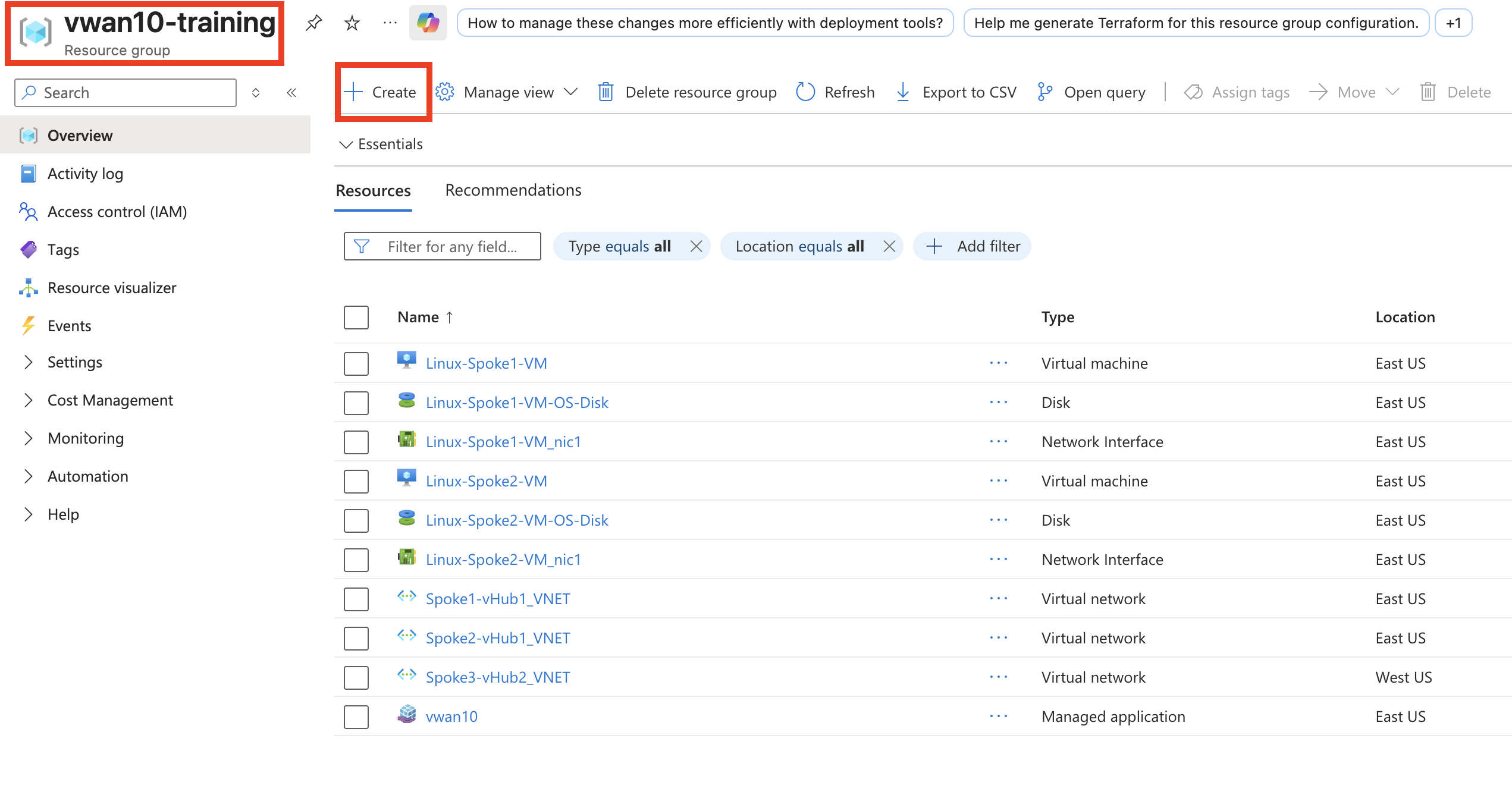
Navigate into your assigned Resource Group and click on the + Create located at the top left of the tool bar.
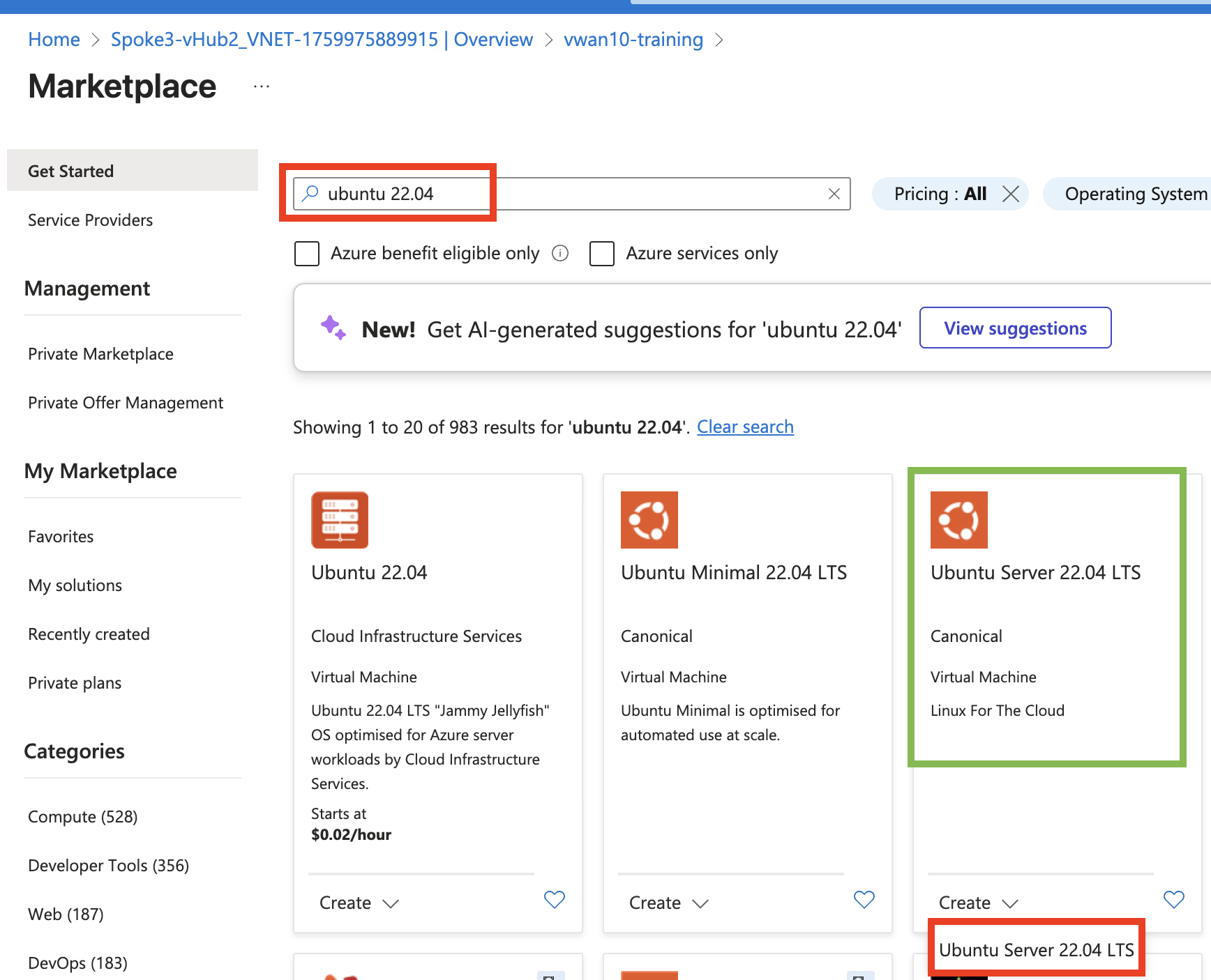
You will be redirected to the Azure Marketplace.
Enter - **ubuntu 24.04 - in the Marketplace search bar, then press enter. Navigate to the Ubuntu 22.04 LTS offering from Canonical and select Create and Ubuntu Server 24.04.
You will be redirected to the Create a virtual machine template.
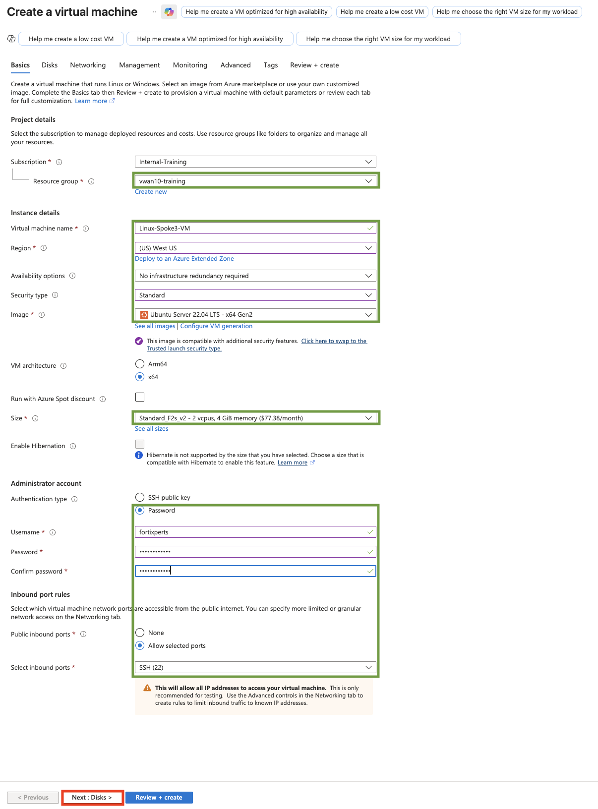
Under the Basics tab, update the following fields:
(Leave the default entry for the other fields not listed here)
Resource group: Confirm vwanXX-training
Virtual machine name: Linux-Spoke3-VM
Region: (US) West US
Availability options: No infrastructure redundancy required
Security type: Standard
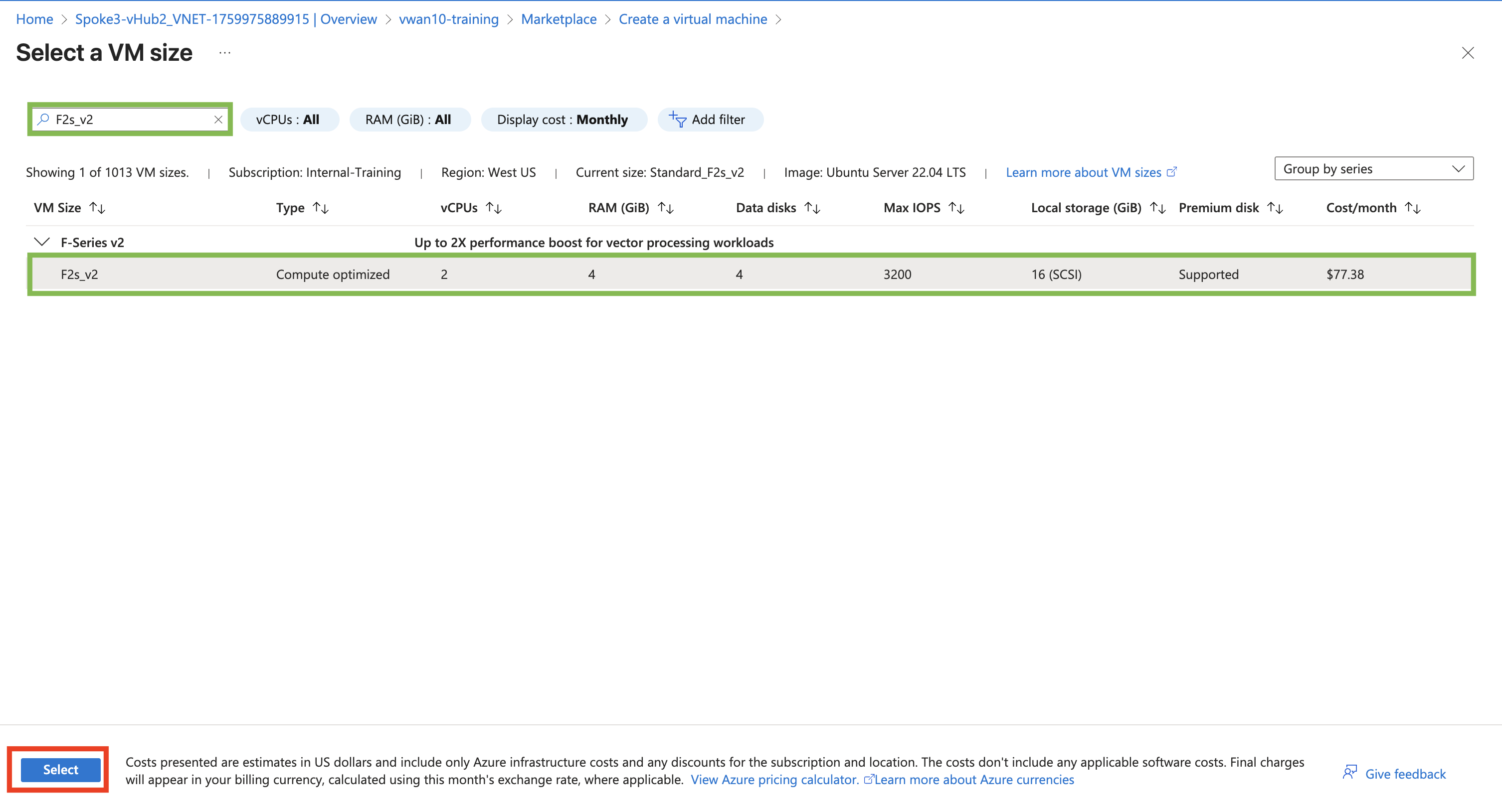
Size: Click “See all sizes”
Search for “F2s_v2”
Click on the VM to highlight
Click the “Select” button
Authentication type: Password
Username: fortixperts
Password: fortiXperts!
Confirm password: fortiXperts!
Confirm the changes and the other fields default entries match the following diagram.
ClickNext: Disks >
Feel free to read through the available disk services that can be changed/enabled.
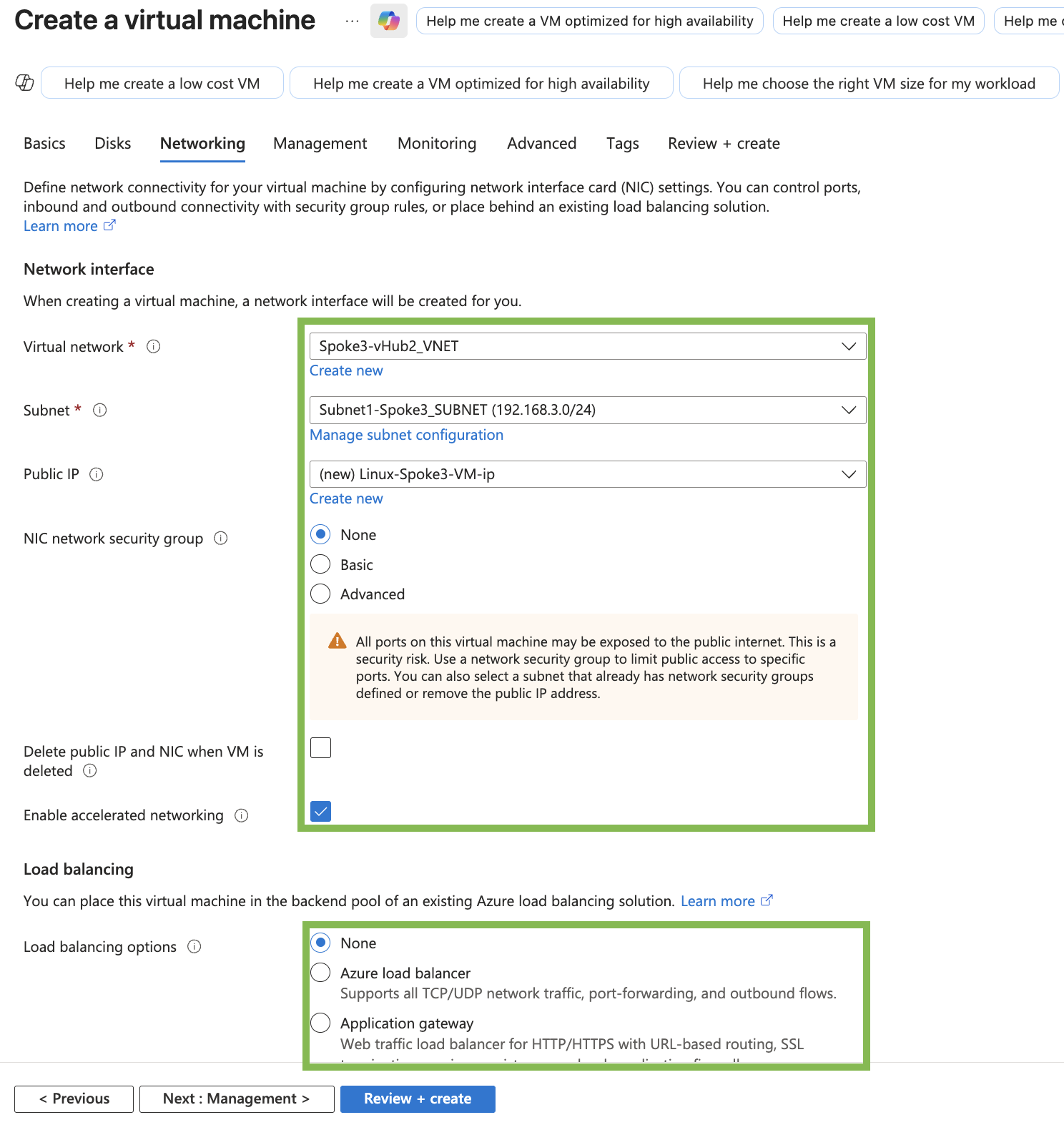
ClickNext: Networking >
Update the following fields on the Networking tab: (Leave the default entry of the other fields not listed here)
Virtual network: “Spoke3-vHub2_VNET”
Subnet: “Subnet1-Spoke3_SUBNET (192.168.3.0/24)”
Public IP: Select None
NIC network security group: Select None
Confirm the changes and the other fields default entries match the following diagram
ClickReview + create >
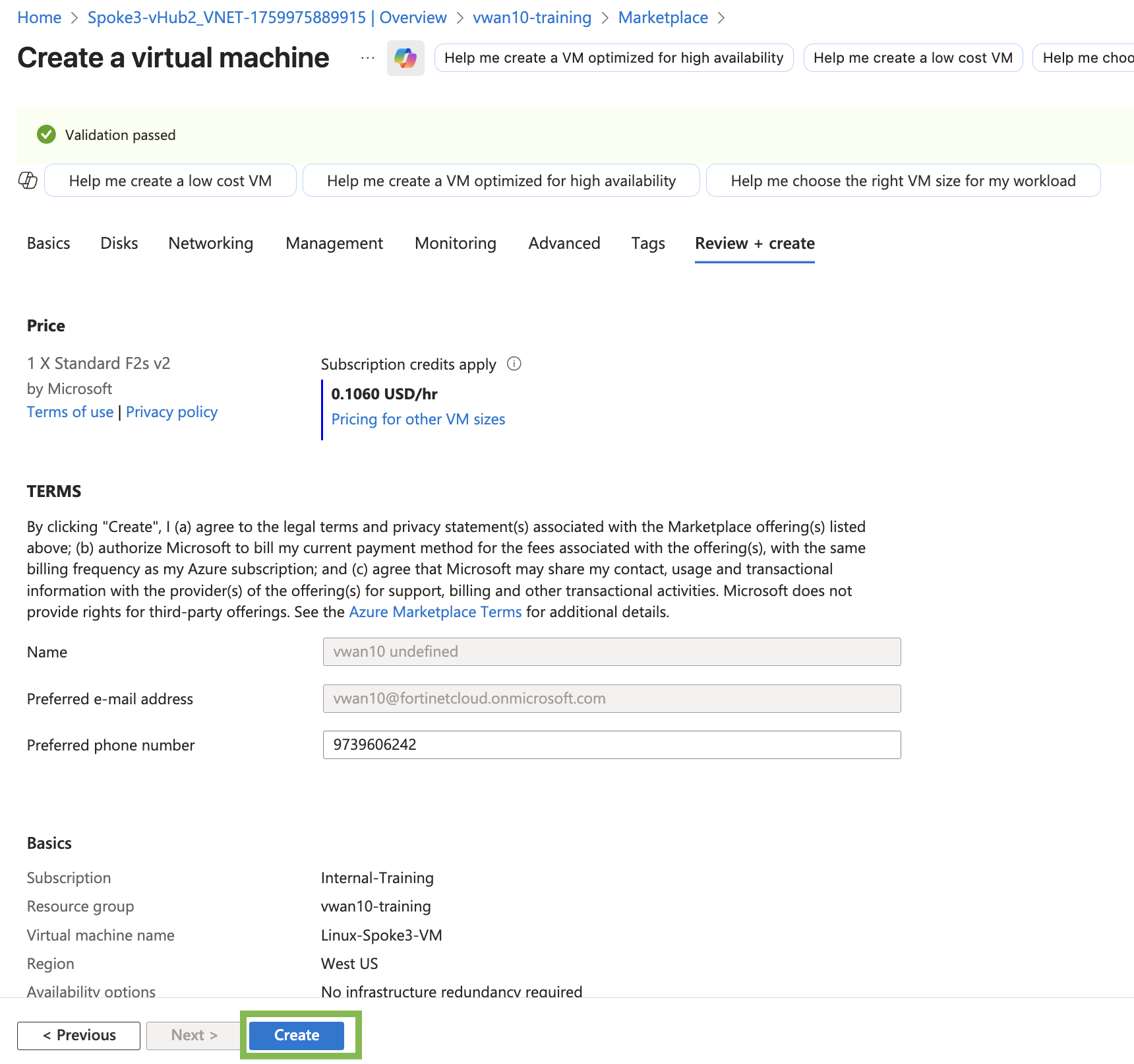
Feel free to read through the Management, Monitoring, Advanced, and Tags tabs for additional services that can be changed/enabled.
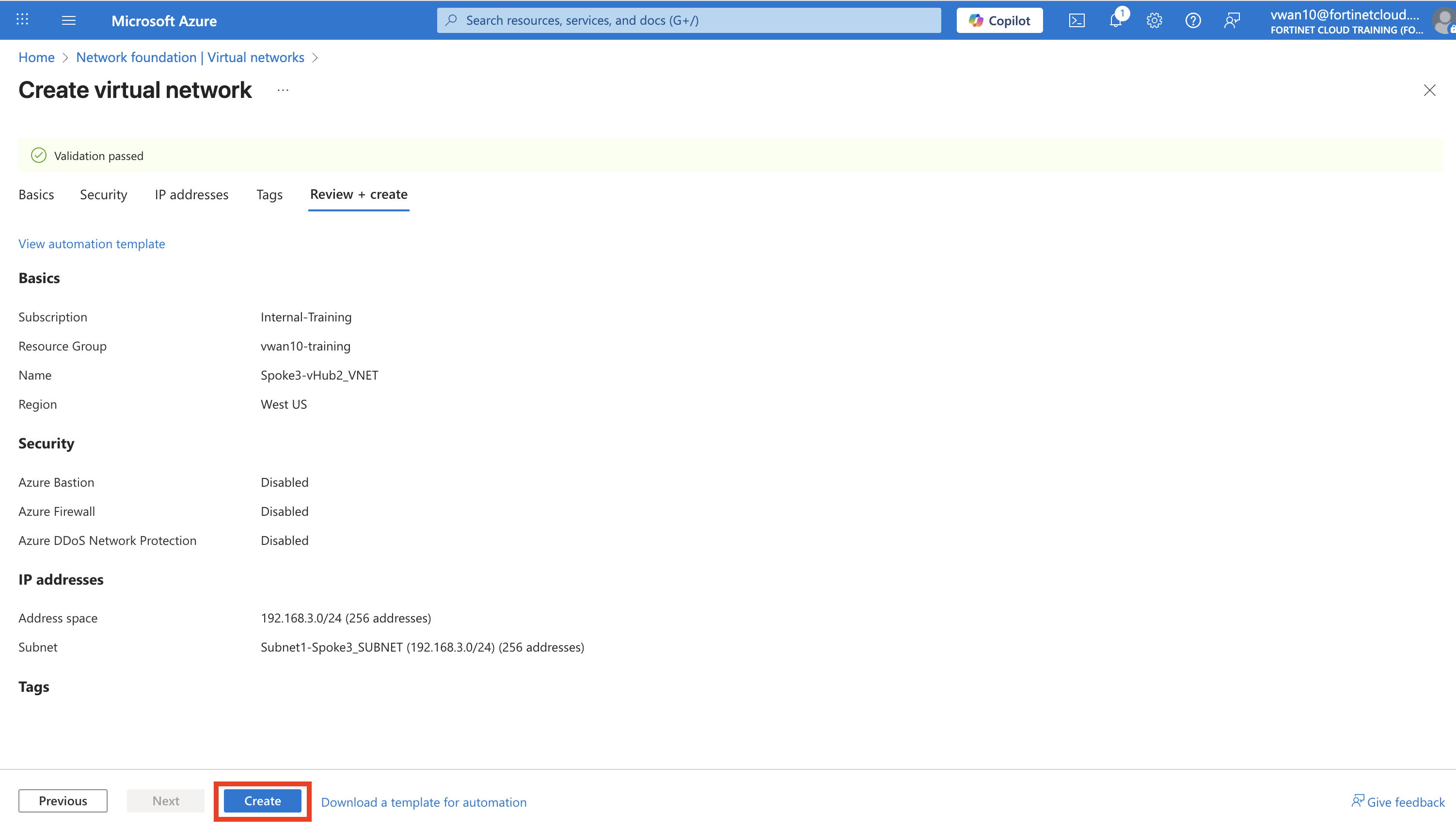
Confirm the template validation has passed
ClickCreate
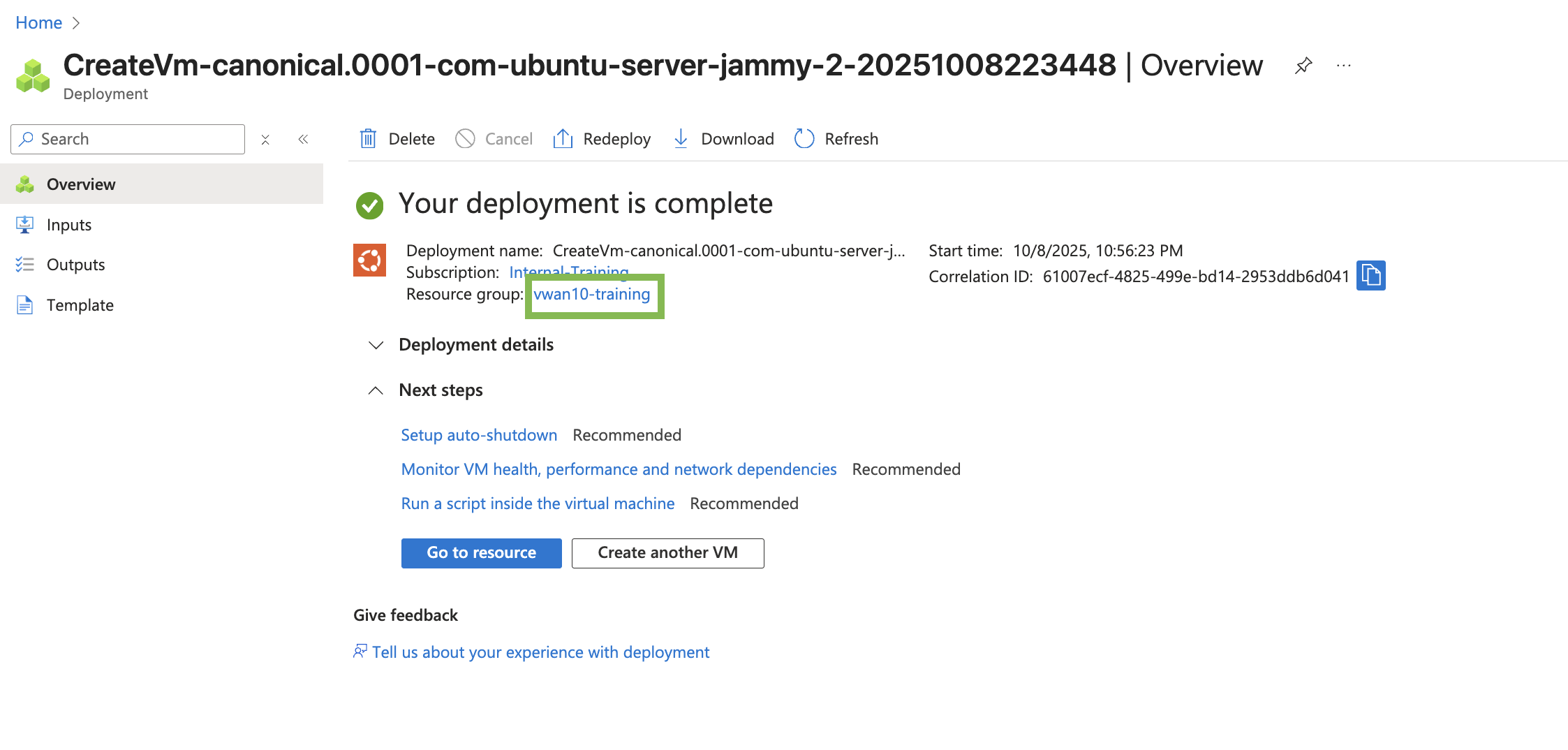
Info
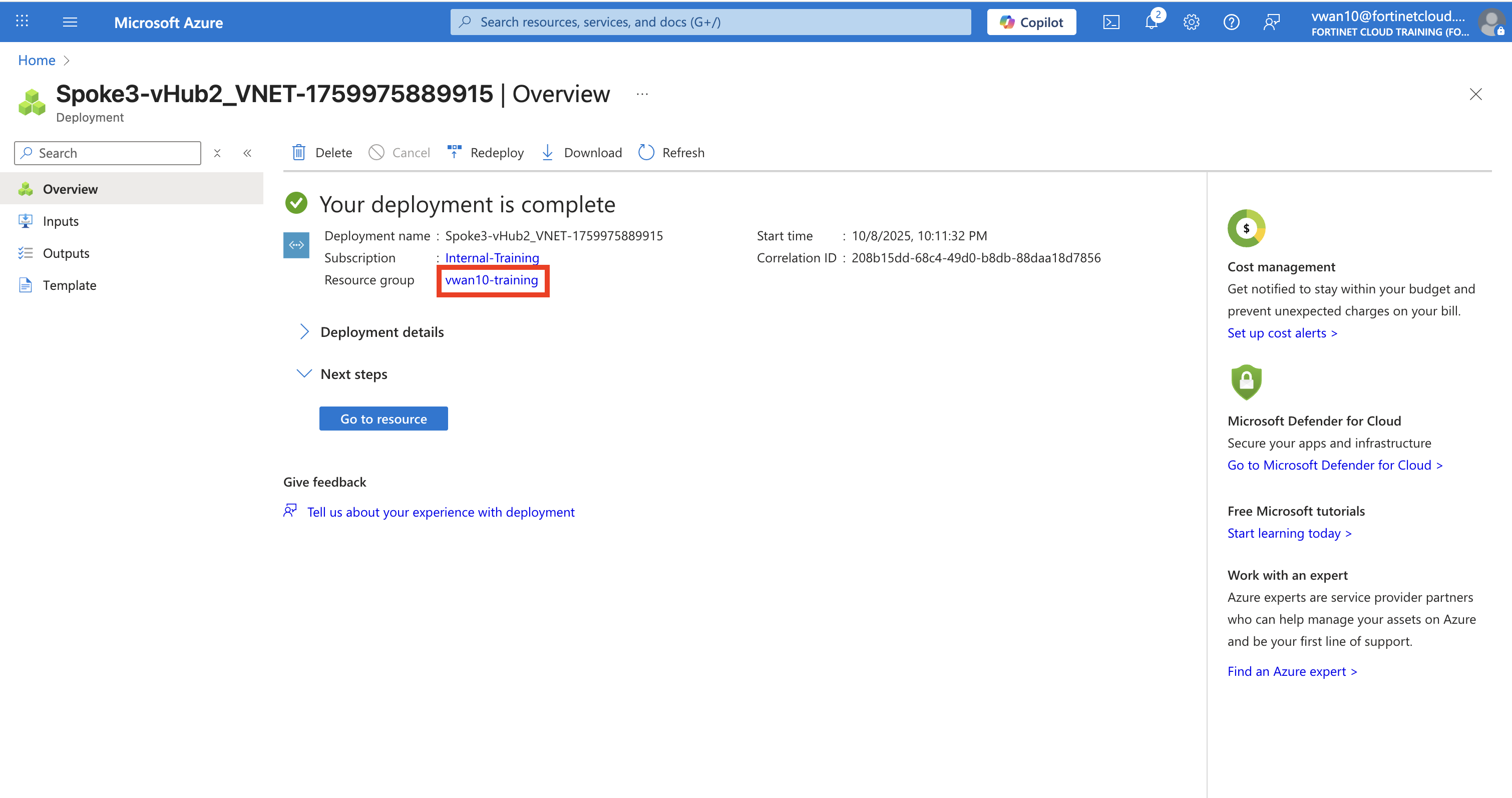
The Deployment is in progress notice is displayed and then the Your deployment is complete notice is displayed.
Click on the vwanXX-training link to be re-directed to your resource group.
Verify the new Linux-Spoke3-VM and the associated components are listed in your Resource Group.
Continue to Chapter 6 - Task 4: VNET Peering to the Second Hub
Task 4: VNET Peering to the Second Hub
In this task setup peering between the Spoke3-vHub2_VNET and the vwanXX-westus-vHub2_VHUB. View route tables on the FortiGate NVAs, hubs, and the Linux-Spoke3-VM.
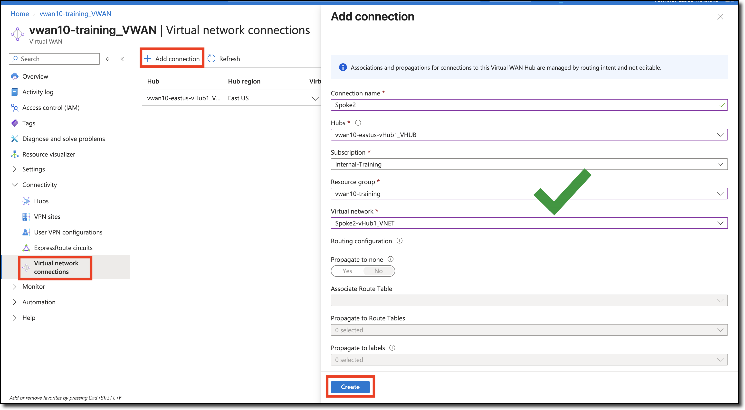
Peer Spoke3-vHub2_VNET to vwanXX-westus-vHub2_VHUB
Navigate to your Virtual Wan - vwanXX-training_VWAN
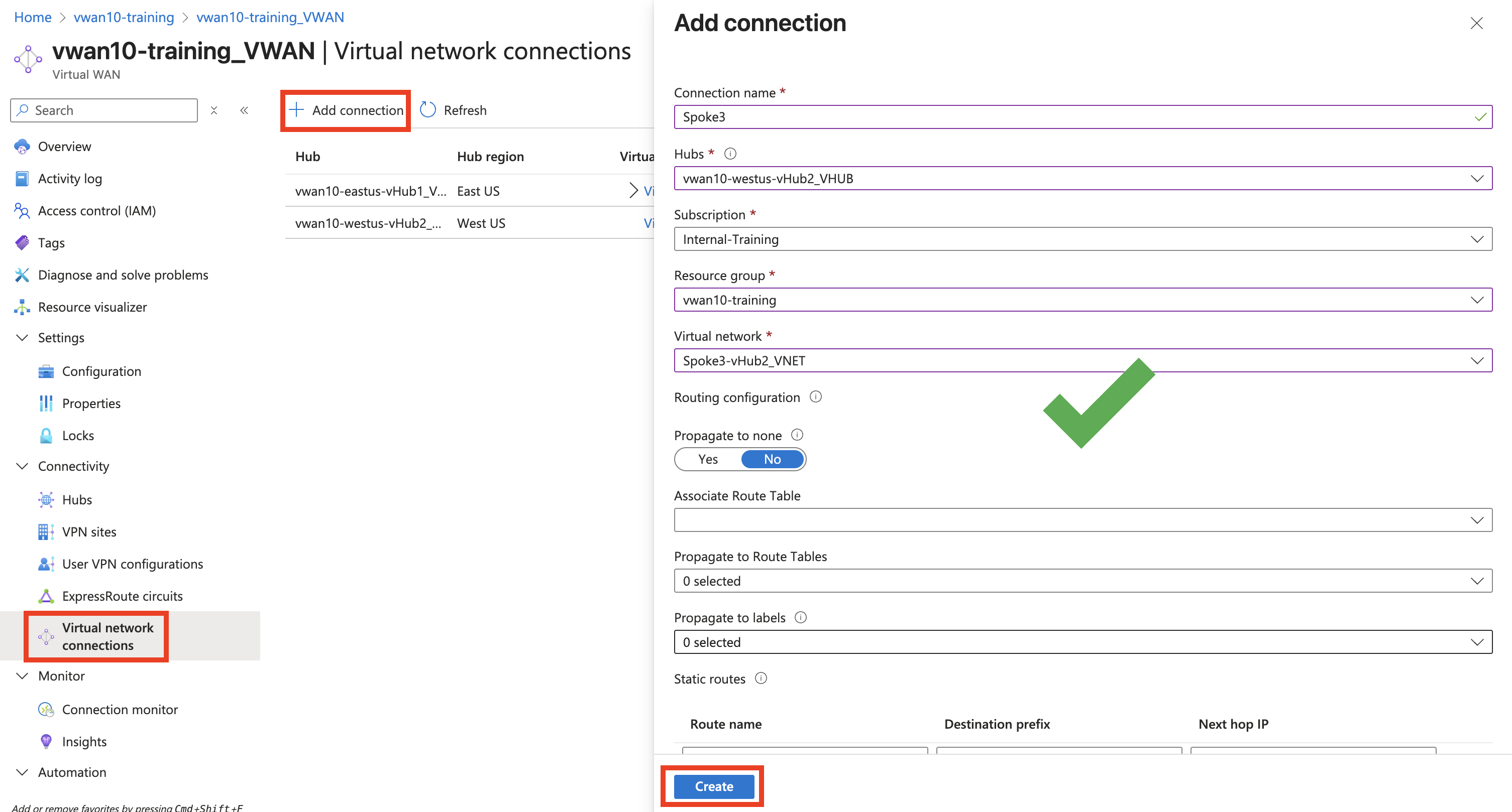
Click “Virtual network connections” on the left under “Connectivity”.
Click “+ Add connection”
Enter - “Connection name” - Spoke3
Select - “Hubs” - your second hub -vwanXX-westus-vHub2_VHUB
Select - “Resource group” - your resource group - vwanXX-training
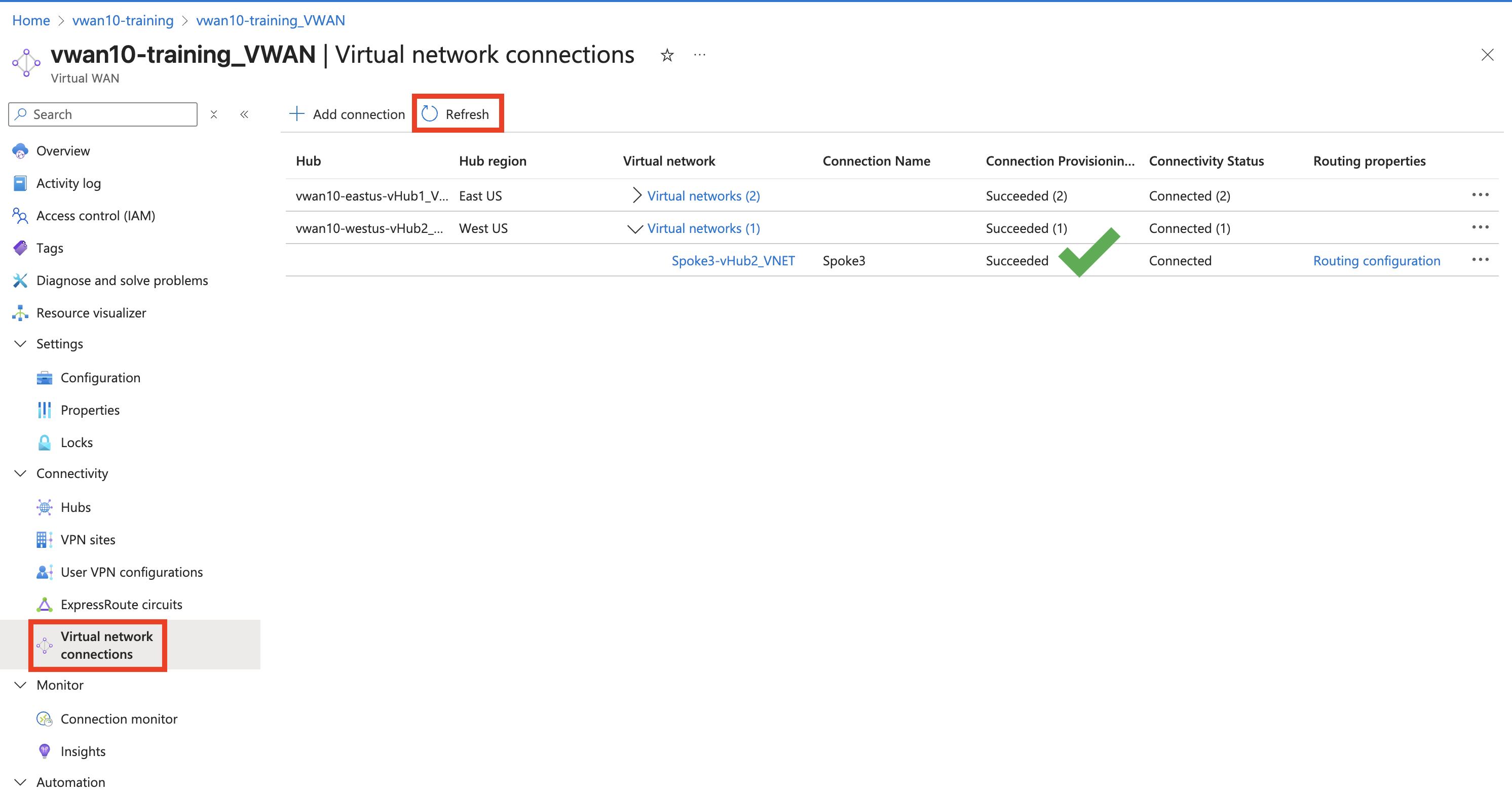
VNET Peering takes a few minutes to complete. The Connectivity Status can be updated by Clicking Refresh
Verify Route Tables
Now that the Spoke3-vHub2_VNET has been peered to your second hub vwanXX-westus-vHub2_VHUB and both hubs are part of the Azure vWAN, lets take a closer look at the learned routes in each resource.
What routes do the FortiGates know about?
What are the effective routes of both hubs?
What are the effective routes of the Linux-Spoke3-VM?
View each FortiGate’s route table
Open each FortiGate in a browser tab/window
Open FortiGate CLI
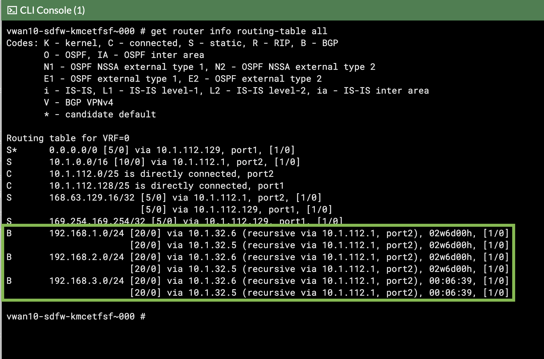
Run CLI command get router info routing-table all
The output shows that BGP learned routes for the new Spoke3-vHub2_VNET peered to the new vwanXX-westus-vHub2_VHUB.
View the effective routes of the default route table, in both hubs.
vHub1
Navigate to your vWAN hub - vwanXX-eastus-vHub1_VHUB
On the left side, expand “Routing” and then “Effective Routes”
Select - “Route Tables” under “Choose resource type”
Select - “Default” under “Resource”
All effective routes should have the FortiGate NVA group as next hop.Note that nothing has changed in your vwanXX-eastus-vHub1_VHUB route table.
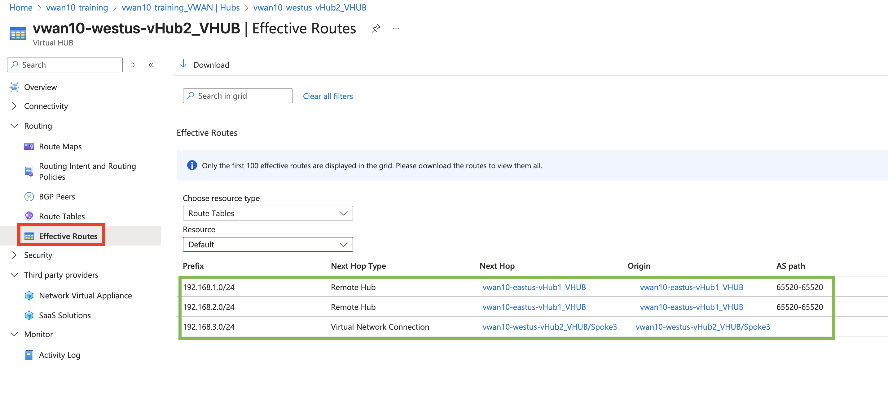
vHub2
Navigate to your vWAN hub - vwanXX-westus-vHub2_VHUB
On the left side, expand “Routing” and then “Effective Routes”
Select - “Route Tables” under “Choose resource type”
Select - “Default” under “Resource”
Note the three spoke VNETs learned by vHub2.
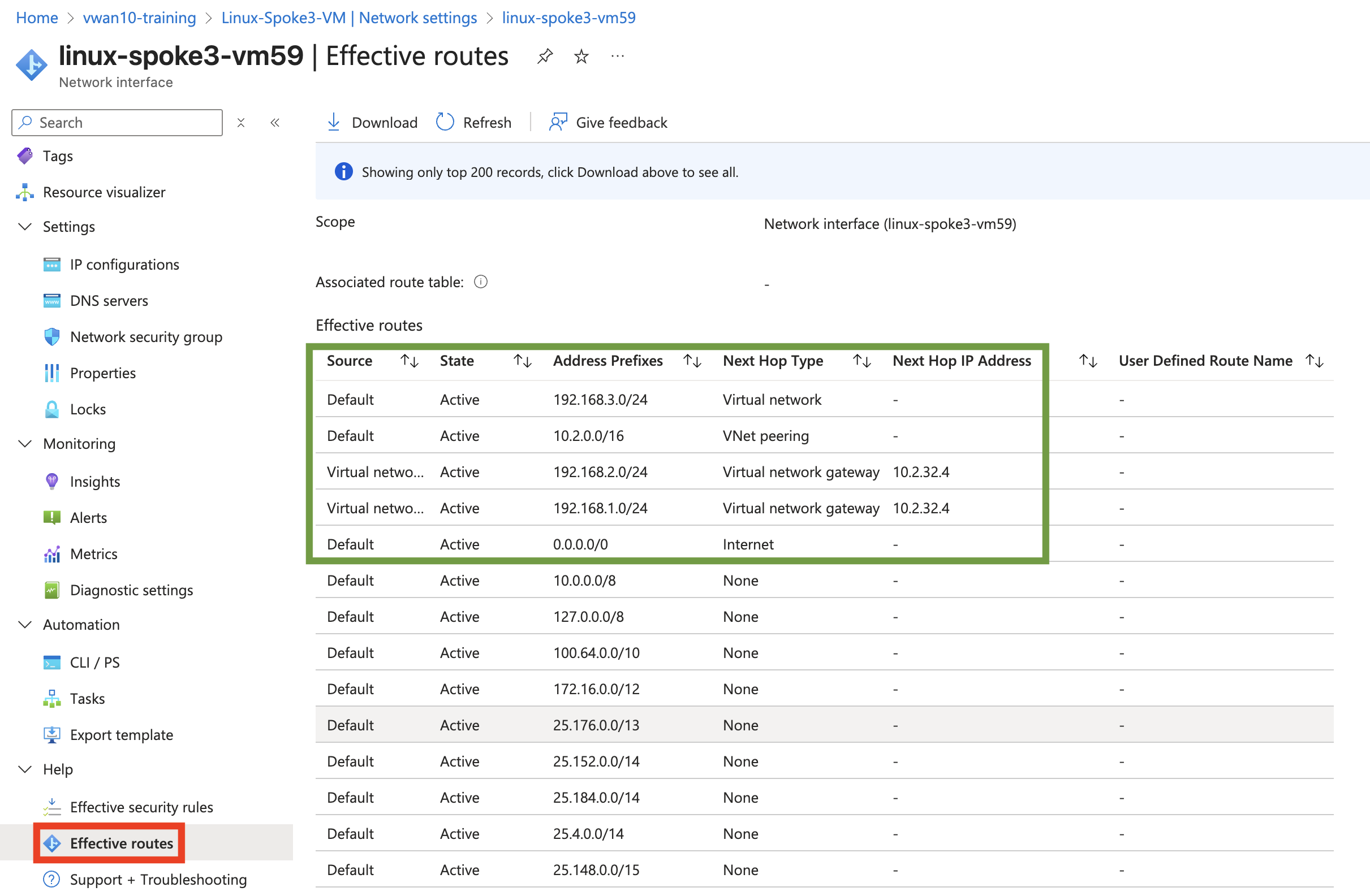
View the effective routes on the “Linux-Spoke3-VM”
Navigate to your Linux VM Linux-Spoke3-VM
Click - “Network settings” located under “Networking” on the left side of the page