Subsections of Autoscale Reference
Internet Egress Options
Overview
The FortiGate autoscale solution provides two distinct architectures for internet egress traffic, each optimized for different operational requirements and cost considerations.
Option 1: Elastic IP (EIP) per Instance
Each FortiGate instance in the autoscale group receives a dedicated Elastic IP address. All traffic destined for the public internet is source-NATed behind the instance’s assigned EIP.
Configuration
access_internet_mode = "eip"
Architecture Behavior
In EIP mode, the architecture routes all internet-bound traffic to port2 (the public interface). The route table for the public subnet directs traffic to the Internet Gateway (IGW), where automatic source NAT to the associated EIP occurs.
Advantages
- No NAT Gateway costs: Eliminates monthly NAT Gateway charges ($0.045/hour + data processing)
- Distributed egress: Each instance has independent internet connectivity
- Simplified troubleshooting: Per-instance source IP simplifies traffic flow analysis
- No single point of failure: Loss of one instance’s EIP doesn’t affect others
Considerations
- Unpredictable IP addresses: EIPs are allocated from AWS’s pool; you cannot predict or specify the assigned addresses
- Allowlist complexity: Destinations requiring IP allowlisting must accommodate a pool of EIPs (one per maximum autoscale capacity)
- IP churn during scaling: Scale-out events introduce new source IPs; scale-in events remove them
- Limited EIP quota: AWS accounts have default limits (5 EIPs per region, increased upon request)
Best Use Cases
- Cost-sensitive deployments where NAT Gateway charges exceed EIP allocation costs
- Environments where destination allowlisting is not required
- Architectures prioritizing distributed egress over consistent source IPs
- Development and testing environments with limited budget
Option 2: NAT Gateway
All FortiGate instances share one or more NAT Gateways deployed in public subnets. Traffic is source-NATed to the NAT Gateway’s static Elastic IP address.
Configuration
access_internet_mode = "nat_gw"
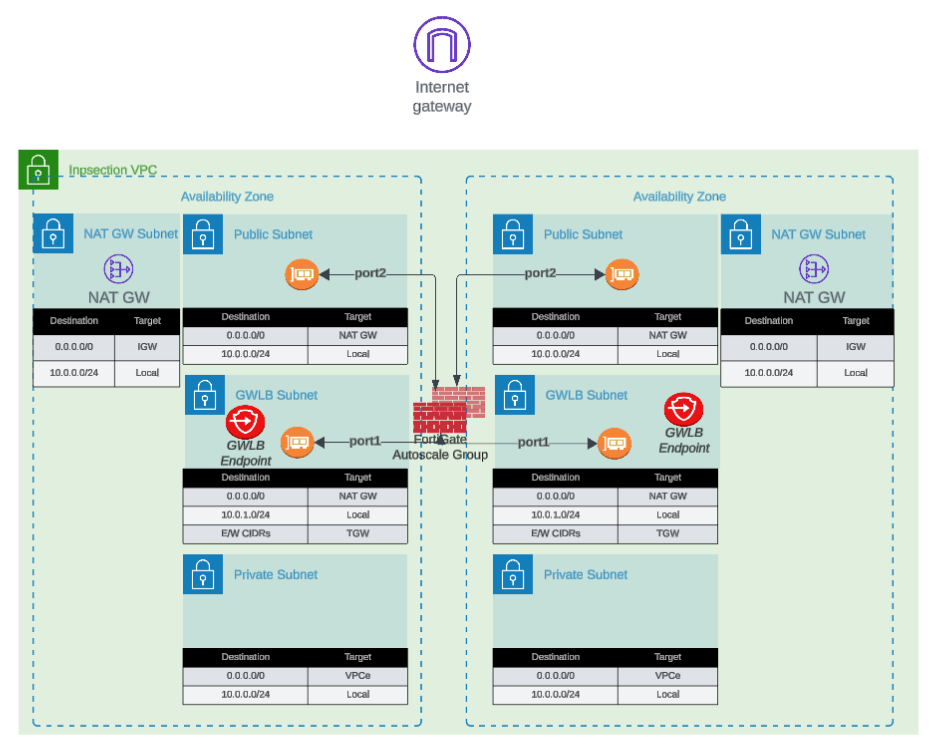
Architecture Behavior
NAT Gateway mode requires additional subnet and route table configuration. Internet-bound traffic is first routed to the NAT Gateway in the public subnet, which performs source NAT to its static EIP before forwarding to the IGW.
Advantages
- Predictable source IP: Single, stable public IP address for the lifetime of the NAT Gateway
- Simplified allowlisting: Destinations only need to allowlist one IP address (per Availability Zone)
- High throughput: NAT Gateway supports up to 45 Gbps per AZ
- Managed service: AWS handles NAT Gateway scaling and availability
- Independent of FortiGate scaling: Source IP remains constant during scale-in/scale-out events
Considerations
- Additional costs: $0.045/hour per NAT Gateway + $0.045 per GB data processed
- Per-AZ deployment: Multi-AZ architectures require NAT Gateway in each AZ for fault tolerance
- Additional subnet requirements: Requires dedicated NAT Gateway subnet in each AZ
- Route table complexity: Additional route tables needed for NAT Gateway routing
Cost Analysis Example
Scenario: 4 FortiGate instances processing 10 TB/month egress traffic
EIP Mode:
- 4 EIP allocations: $0 (first EIP free, then $0.00/hour per EIP)
- Total monthly: ~$0 (minimal costs)
NAT Gateway Mode (2 AZs):
- 2 NAT Gateways: 2 x $0.045/hour x 730 hours = $65.70
- Data processing: 10,000 GB x $0.045 = $450.00
- Total monthly: $515.70
Decision Point: NAT Gateway makes sense when consistent source IP requirement justifies the additional cost.
Best Use Cases
- Production environments requiring predictable source IPs
- Compliance scenarios where destination IP allowlisting is mandatory
- High-volume egress traffic to SaaS providers with IP allowlisting requirements
- Architectures where operational simplicity outweighs additional cost
Decision Matrix
| Factor | EIP Mode | NAT Gateway Mode |
|---|
| Monthly Cost | Minimal | $500+ (varies with traffic) |
| Source IP Predictability | Variable (changes with scaling) | Stable |
| Allowlisting Complexity | High (multiple IPs) | Low (single IP per AZ) |
| Throughput | Per-instance limit | Up to 45 Gbps per AZ |
| Operational Complexity | Low | Medium |
| Best For | Dev/test, cost-sensitive | Production, compliance-driven |
Next Steps
After selecting your internet egress option, proceed to Firewall Architecture to configure the FortiGate interface model.
Firewall Architecture
Overview
FortiGate instances can operate in single-arm (1-ARM) or dual-arm (2-ARM) network configurations, fundamentally changing traffic flow patterns through the firewall.
Configuration
firewall_policy_mode = "1-arm" # or "2-arm"
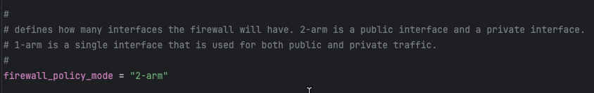
2-ARM Configuration (Recommended for Most Deployments)
Architecture Overview
The 2-ARM configuration deploys FortiGate instances with distinct “trusted” (private) and “untrusted” (public) interfaces, providing clear network segmentation.
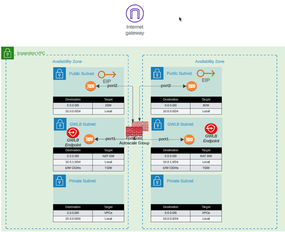
Traffic Flow:
- Traffic arrives at GWLB Endpoints (GWLBe) in the inspection VPC
- GWLB load-balances traffic across healthy FortiGate instances
- Traffic encapsulated in Geneve tunnels arrives at FortiGate port1 (data plane)
- FortiGate inspects traffic and applies security policies
- Internet-bound traffic exits via port2 (public interface)
- Port2 traffic is source-NATed via EIP or NAT Gateway
- Return traffic follows reverse path back through Geneve tunnels
Interface Assignments
- port1: Data plane interface for GWLB connectivity (Geneve tunnel termination)
- port2: Public interface for internet egress (with optional dedicated management when enabled)
Network Interfaces Visualization
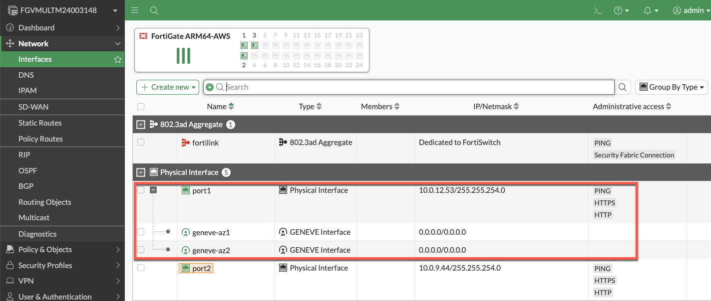
The FortiGate GUI displays both physical interfaces and logical Geneve tunnel interfaces. Traffic inspection occurs on the logical tunnel interfaces, while physical port2 handles egress.
Advantages
- Clear network segmentation: Separate trusted and untrusted zones
- Traditional firewall model: Familiar architecture for network security teams
- Simplified policy creation: North-South policies align with interface direction
- Better traffic visibility: Distinct ingress/egress paths ease troubleshooting
- Dedicated management option: Port2 can be isolated for management traffic
Best Use Cases
- Production deployments requiring clear network segmentation
- Environments with security policies mandating separate trusted/untrusted zones
- Architectures where dedicated management interface is required
- Standard north-south inspection use cases
1-ARM Configuration
Architecture Overview
The 1-ARM configuration uses a single interface (port1) for all data plane traffic, eliminating the need for a second network interface.
Traffic Flow:
- Traffic arrives at port1 encapsulated in Geneve tunnels from GWLB
- FortiGate inspects traffic and applies security policies
- Traffic is hairpinned back through the same Geneve tunnel it arrived on
- Traffic returns to originating distributed VPC through GWLB
- Distributed VPC uses its own internet egress path (IGW/NAT Gateway)
This “bump-in-the-wire” architecture is the typical 1-ARM pattern for distributed inspection, where the FortiGate provides security inspection but traffic egresses from the spoke VPC, not the inspection VPC.
Important Behavior: Stateful Load Balancing
GWLB Statefulness: The Gateway Load Balancer maintains connection state tables for traffic flows.
Primary Traffic Pattern (Distributed Architecture):
- Traffic enters via Geneve tunnel –> FortiGate inspection –> Hairpins back through same Geneve tunnel
- Distributed VPC handles actual internet egress via its own IGW/NAT Gateway
- This “bump-in-the-wire” model provides security inspection without routing traffic through inspection VPC
Key Requirement: Symmetric routing through the GWLB. Traffic must return via the same Geneve tunnel it arrived on to maintain proper state table entries.
Info
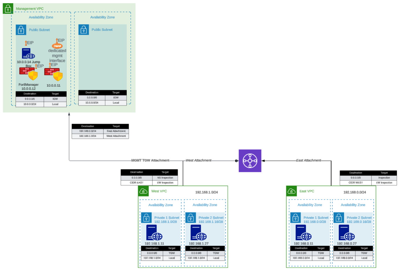
Centralized Egress Architecture (Transit Gateway Pattern)
In centralized egress deployments with Transit Gateway, the traffic flow is fundamentally different and represents the primary use case for internet egress through the inspection VPC:
Traffic Flow:
- Spoke VPC traffic routes to Transit Gateway
- TGW routes traffic to inspection VPC
- Traffic enters GWLBe (same AZ to avoid cross-AZ charges)
- GWLB forwards traffic through Geneve tunnel to FortiGate
- FortiGate inspects traffic and applies security policies
- Traffic exits port1 (1-ARM) or port2 (2-ARM) toward internet
- Egress via EIP or NAT Gateway in inspection VPC
- Response traffic returns via same interface to same Geneve tunnel
This is the standard architecture for centralized internet egress where:
- All spoke VPCs route internet-bound traffic through the inspection VPC
- FortiGate autoscale group provides centralized security inspection AND NAT
- Single egress point simplifies security policy management and reduces costs
- Requires careful route table configuration to maintain symmetric routing
When to use: Centralized egress architectures where spoke VPCs do NOT have their own internet gateways.
Note
Distributed Architecture - Alternative Pattern (Advanced Use Case)
In distributed architectures where spoke VPCs have their own internet egress, it is possible (but not typical) to configure traffic to exit through the inspection VPC instead of hairpinning:
- Traffic enters via Geneve tunnel –> Exits port1 to internet –> Response returns via port1 to same Geneve tunnel
This pattern requires:
- Careful route table configuration in the inspection VPC
- Specific firewall policies on the FortiGate
- Proper symmetric routing to maintain GWLB state tables
This is rarely used in distributed architectures since spoke VPCs typically handle their own egress. The standard bump-in-the-wire pattern (hairpin through same Geneve tunnel) is recommended when spoke VPCs have internet gateways.
Interface Assignments
- port1: Combined data plane (Geneve) and egress (internet) interface
Advantages
- Reduced complexity: Single interface simplifies routing and subnet allocation
- Lower costs: Fewer ENIs to manage and potential for smaller instance types
- Simplified subnet design: Only requires one data subnet per AZ
Considerations
- Hairpinning pattern: Traffic typically hairpins back through same Geneve tunnel
- Higher port1 bandwidth requirements: All traffic flows through single interface (both directions)
- Limited management options: Cannot enable dedicated management ENI in true 1-ARM mode
- Symmetric routing requirement: All traffic must egress and return via port1 for proper state table maintenance
Best Use Cases
- Cost-optimized deployments with lower throughput requirements
- Simple north-south inspection without management VPC integration
- Development and testing environments
- Architectures where simplified subnet design is prioritized
Comparison Matrix
| Factor | 1-ARM | 2-ARM |
|---|
| Interfaces Required | 1 (port1) | 2 (port1 + port2) |
| Network Complexity | Lower | Higher |
| Cost | Lower | Slightly higher |
| Management Isolation | Not available | Available |
| Traffic Pattern | Hairpin (distributed) or egress (centralized) | Clear ingress/egress separation |
| Best For | Simple deployments, cost optimization | Production, clear segmentation |
Next Steps
After selecting your firewall architecture, proceed to Dedicated Management ENI to learn about management plane isolation options.
Management Isolation Options
Overview
The FortiGate autoscale solution provides multiple approaches to isolating management traffic from data plane traffic, ranging from shared interfaces to complete physical network separation.
This page covers three progressive levels of management isolation, allowing you to choose the appropriate security posture for your deployment requirements.
Option 1: Combined Data + Management (Default)
Architecture Overview
In the default configuration, port2 serves dual purposes:
- Data plane: Internet egress for inspected traffic (in 2-ARM mode)
- Management plane: GUI, SSH, SNMP access
Configuration
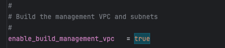
enable_dedicated_management_eni = false
enable_dedicated_management_vpc = false
Characteristics
- Simplest configuration: No additional interfaces or VPCs required
- Lower cost: Minimal infrastructure overhead
- Shared security groups: Same rules govern data and management traffic
- Single failure domain: Management access tied to data plane availability
When to Use
- Development and testing environments
- Proof-of-concept deployments
- Budget-constrained projects
- Simple architectures without compliance requirements
Option 2: Dedicated Management ENI
Architecture Overview
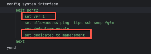
Port2 is removed from the data plane and dedicated exclusively to management functions. FortiOS configures the interface with set dedicated-to management, placing it in an isolated VRF with independent routing.
Configuration
enable_dedicated_management_eni = true
How It Works
- Dedicated-to attribute: FortiOS configures port2 with
set dedicated-to management - Separate VRF: Port2 is placed in an isolated VRF with independent routing table
- Policy restrictions: FortiGate prevents creation of firewall policies using port2
- Management-only traffic: GUI, SSH, SNMP, and FortiManager/FortiAnalyzer connectivity
FortiOS Configuration Impact
The dedicated management ENI can be verified in the FortiGate GUI:
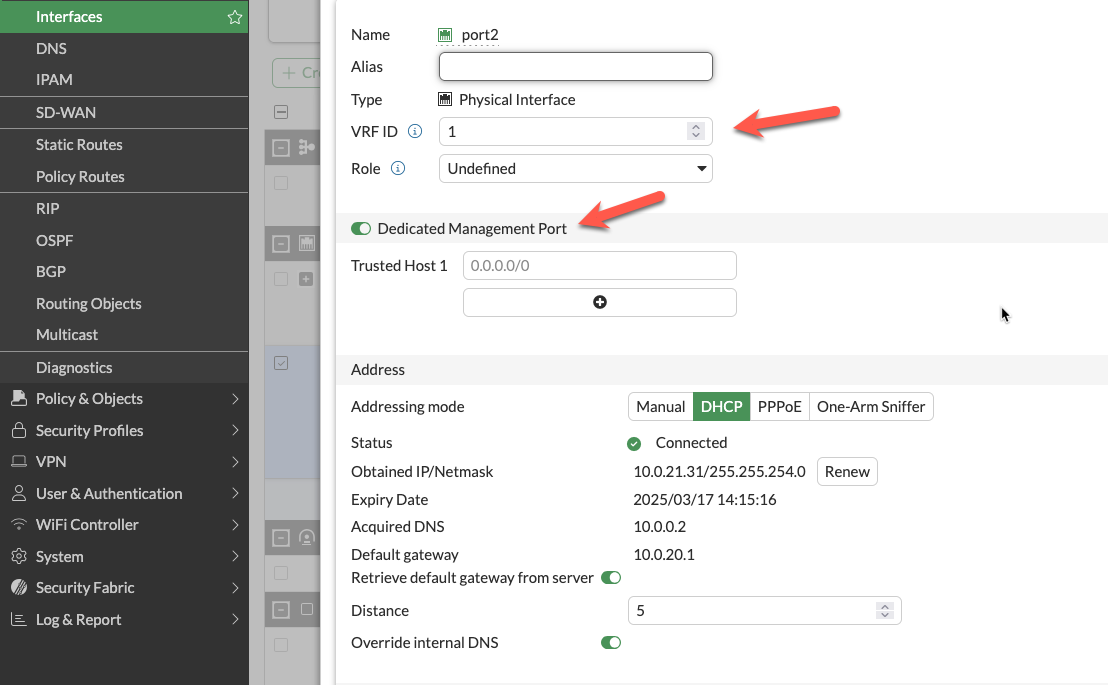
The interface shows the dedicated-to: management attribute and separate VRF assignment, preventing data plane traffic from using this interface.
Important Compatibility Notes
Warning
Critical Limitation: 2-ARM + NAT Gateway + Dedicated Management ENI
When combining:
firewall_policy_mode = "2-arm"access_internet_mode = "nat_gw"enable_dedicated_management_eni = true
Port2 will NOT receive an Elastic IP address. This is a valid configuration, but imposes connectivity restrictions:
- Cannot access FortiGate management from public internet
- Can access via private IP through AWS Direct Connect or VPN
- Can access via management VPC (see Option 3 below)
If you require public internet access to the FortiGate management interface with NAT Gateway egress, either:
- Use
access_internet_mode = "eip" (assigns EIP to port2) - Use dedicated management VPC with separate internet connectivity (Option 3)
- Implement AWS Systems Manager Session Manager for private connectivity
Characteristics
- Clear separation of concerns: Management traffic isolated from data plane
- Independent security policies: Separate security groups for management interface
- Enhanced security posture: Reduces attack surface on management plane
- Moderate complexity: Requires additional subnet and routing configuration
When to Use
- Production deployments requiring management isolation
- Security-conscious environments
- Architectures without dedicated management VPC
- Compliance requirements for management plane separation
Option 3: Dedicated Management VPC (Full Isolation)
Architecture Overview
The dedicated management VPC provides complete physical network separation by deploying FortiGate management interfaces in an entirely separate VPC from the data plane.
Configuration
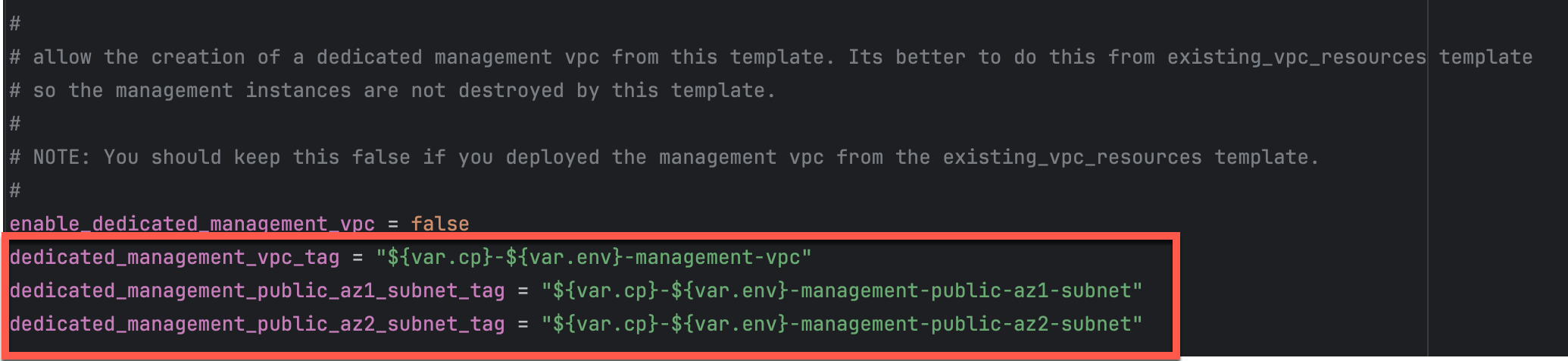
enable_dedicated_management_vpc = true
dedicated_management_vpc_tag = "your-mgmt-vpc-tag"
dedicated_management_public_az1_subnet_tag = "your-az1-subnet-tag"
dedicated_management_public_az2_subnet_tag = "your-az2-subnet-tag"
Benefits
- Physical network separation: Management traffic never traverses inspection VPC
- Independent internet connectivity: Management VPC has dedicated IGW or VPN
- Centralized management infrastructure: FortiManager and FortiAnalyzer deployed in management VPC
- Separate security controls: Management VPC security groups independent of data plane
- Isolated failure domains: Management VPC issues don’t affect data plane
Management VPC Creation Options
Option A: Created by existing_vpc_resources Template (Recommended)
The existing_vpc_resources template creates the management VPC with standardized tags that the simplified template automatically discovers.
Advantages:
- Management VPC lifecycle independent of inspection VPC
- FortiManager/FortiAnalyzer persistence across inspection VPC redeployments
- Separation of concerns for infrastructure management
Default Tags (automatically created):
Configuration (terraform.tfvars):
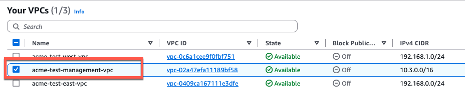
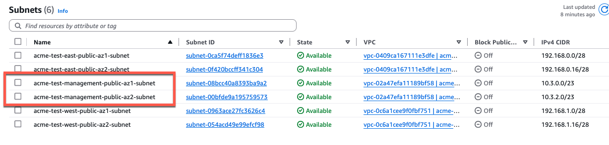
enable_dedicated_management_vpc = true
dedicated_management_vpc_tag = "acme-test-management-vpc"
dedicated_management_public_az1_subnet_tag = "acme-test-management-public-az1-subnet"
dedicated_management_public_az2_subnet_tag = "acme-test-management-public-az2-subnet"
Option B: Use Existing Management VPC
If you have an existing management VPC with custom tags, configure the template to discover it:
Configuration:
enable_dedicated_management_vpc = true
dedicated_management_vpc_tag = "my-custom-mgmt-vpc-tag"
dedicated_management_public_az1_subnet_tag = "my-custom-mgmt-public-az1-tag"
dedicated_management_public_az2_subnet_tag = "my-custom-mgmt-public-az2-tag"
The template uses these tags to locate the management VPC and subnets via Terraform data sources.
Behavior When Enabled
When enable_dedicated_management_vpc = true:
- Automatic ENI creation: Template creates dedicated management ENI (port2) in management VPC subnets
- Implies dedicated management ENI: Automatically sets
enable_dedicated_management_eni = true - VPC peering/TGW: Management VPC must have connectivity to inspection VPC for HA sync
- Security group creation: Appropriate security groups created for management traffic
Network Connectivity Requirements
Management VPC –> Inspection VPC Connectivity:
- Required for FortiGate HA synchronization between instances
- Typically implemented via VPC peering or Transit Gateway attachment
- Must allow TCP port 443 (HA sync), TCP 22 (SSH), ICMP (health checks)
Management VPC –> Internet Connectivity:
- Required for FortiGuard services (signature updates, licensing)
- Required for administrator access to FortiGate management interfaces
- Can be via Internet Gateway, NAT Gateway, or AWS Direct Connect
Characteristics
- Highest security posture: Complete physical isolation
- Greatest flexibility: Independent infrastructure lifecycle
- Higher complexity: Requires VPC peering or TGW configuration
- Additional cost: Separate VPC infrastructure and data transfer charges
When to Use
- Enterprise production deployments
- Strict compliance requirements (PCI-DSS, HIPAA, etc.)
- Multi-account AWS architectures
- Environments with dedicated management infrastructure
- Organizations with existing management VPCs for network security appliances
Comparison Matrix
| Factor | Combined (Default) | Dedicated ENI | Dedicated VPC |
|---|
| Security Isolation | Low | Medium | High |
| Complexity | Lowest | Medium | Highest |
| Cost | Lowest | Low | Medium |
| Management Access | Via data plane interface | Via dedicated interface | Via separate VPC |
| Failure Domain Isolation | No | Partial | Complete |
| VPC Peering Required | No | No | Yes |
| Compliance Suitability | Basic | Good | Excellent |
| Best For | Dev/test, simple deployments | Production, security-conscious | Enterprise, compliance-driven |
Decision Tree
Use this decision tree to select the appropriate management isolation level:
1. Is this a production deployment?
|--- No --> Combined Data + Management (simplest)
\--- Yes --> Continue to question 2
2. Do you have compliance requirements for management plane isolation?
|--- No --> Dedicated Management ENI (good balance)
\--- Yes --> Continue to question 3
3. Do you have existing management VPC infrastructure?
|--- Yes --> Dedicated Management VPC (leverage existing)
\--- No --> Evaluate cost/benefit:
|--- High security requirements --> Dedicated Management VPC
\--- Moderate requirements --> Dedicated Management ENI
Deployment Patterns
Pattern 1: Dedicated ENI + EIP Mode
firewall_policy_mode = "2-arm"
access_internet_mode = "eip"
enable_dedicated_management_eni = true
- Port2 receives EIP for public management access
- Suitable for environments without management VPC
- Simplified deployment with direct internet management access
Pattern 2: Dedicated ENI + Management VPC
firewall_policy_mode = "2-arm"
access_internet_mode = "nat_gw"
enable_dedicated_management_vpc = true
dedicated_management_vpc_tag = "my-mgmt-vpc"
- Port2 connects to separate management VPC
- Management VPC has dedicated internet gateway or VPN connectivity
- Preferred for production environments with strict network segmentation
Pattern 3: Combined Management (Default)
firewall_policy_mode = "2-arm"
access_internet_mode = "eip"
enable_dedicated_management_eni = false
- Port2 remains in data plane
- Management access shares public interface with egress traffic
- Simplest configuration but lacks management plane isolation
Best Practices
- Enable dedicated management ENI for production: Provides clear separation of concerns
- Use dedicated management VPC for enterprise deployments: Optimal security posture
- Document connectivity requirements: Ensure operations teams understand access paths
- Test connectivity before production: Verify alternative access methods work
- Plan for failure scenarios: Ensure backup access methods (SSM, VPN) are available
- Use existing_vpc_resources template for management VPC: Separates lifecycle management
- Document tag conventions: Ensure consistent tagging across environments
- Monitor management interface health: Set up CloudWatch alarms for management connectivity
Troubleshooting
Issue: Cannot access FortiGate management interface
Check:
- Security groups allow inbound traffic on management port (443, 22)
- Route tables provide path from your location to management interface
- If using dedicated management VPC, verify VPC peering or TGW is operational
- If using NAT Gateway mode, verify you have alternative access method (VPN, Direct Connect)
Issue: Management interface has no public IP
Cause: Public IP assignment was disabled for the management interface, or using a dedicated management VPC without public subnets.
Note: The access_internet_mode variable only controls how data plane egress traffic leaves the inspection VPC (EIP vs NAT Gateway). It does not affect management interface IP assignment.
Solutions:
- Enable public IP assignment for the management interface in your configuration
- If using dedicated management VPC, ensure the management subnets have routes to an Internet Gateway
- If public management access is not required, access FortiGate via private IP through AWS Direct Connect or VPN
- Use AWS Systems Manager Session Manager for private access
Issue: HA sync not working
Note: HA sync interfaces are always placed in dedicated sync subnets within the inspection VPC to avoid latency. They are never placed in a separate VPC. The dedicated management VPC option only affects the management interfaces (GUI/SSH access), not the HA sync interfaces.
Check:
- Security groups allow TCP 703 (HA heartbeat) and TCP 23 (session sync) between FortiGate instances
- HA sync subnets have proper route tables configured
- Network ACLs permit required traffic between FortiGate sync interfaces
- Verify FortiGate HA configuration matches (HA group name, password, priority settings)
Next Steps
After configuring management isolation, proceed to Licensing Options to choose between BYOL, FortiFlex, or PAYG.
Licensing Options
Overview
The FortiGate autoscale solution supports three distinct licensing models, each optimized for different use cases, cost structures, and operational requirements. You can use a single licensing model or combine them in hybrid configurations for optimal cost efficiency.
Licensing Model Comparison
| Factor | BYOL | FortiFlex | PAYG |
|---|
| Total Cost (12 months) | Lowest | Medium | Highest |
| Upfront Investment | High | Medium | None |
| License Management | Manual (files) | API-driven | None |
| Flexibility | Low | High | Highest |
| Capacity Constraints | Yes (license pool) | Soft (point balance) | None |
| Best For | Long-term, predictable | Variable, flexible | Short-term, simple |
| Setup Complexity | Medium | High | Lowest |
Option 1: BYOL (Bring Your Own License)
Overview
BYOL uses traditional FortiGate-VM license files that you purchase from Fortinet or resellers. The template automates license distribution through S3 bucket storage and Lambda-based assignment.
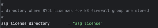
Configuration
asg_license_directory = "asg_license"
asg_byol_asg_min_size = 2
asg_byol_asg_max_size = 4
Directory Structure Requirements
Place BYOL license files in the directory specified by asg_license_directory:
terraform/aws/autoscale_template/
|---- terraform.tfvars
|---- asg_license/
| |---- FGVM01-001.lic
| |---- FGVM01-002.lic
| |---- FGVM01-003.lic
| \---- FGVM01-004.lic
Automated License Assignment
- Terraform uploads
.lic files to S3 during terraform apply - Lambda retrieves available licenses when instances launch
- DynamoDB tracks assignments to prevent duplicates
- Lambda injects license via user-data script
- Licenses return to pool when instances terminate
Critical Capacity Planning
Warning
License Pool Exhaustion
Ensure your license directory contains at minimum licenses equal to asg_byol_asg_max_size.
What happens if licenses are exhausted:
- New BYOL instances launch but remain unlicensed
- Unlicensed instances operate at 1 Mbps throughput
- FortiGuard services will not activate
- If PAYG ASG is configured, scaling continues using on-demand instances
Recommended: Provision 20% more licenses than max_size
Characteristics
- Lowest total cost: Best value for long-term (12+ months)
- Predictable costs: Fixed licensing regardless of usage
- License management: Requires managing physical files
- Upfront investment: Must purchase licenses in advance
When to Use
- Long-term production (12+ months)
- Predictable, steady-state workloads
- Existing FortiGate BYOL licenses
- Cost-conscious deployments
Option 2: FortiFlex (Usage-Based Licensing)
Overview
FortiFlex provides consumption-based, API-driven licensing. Points are consumed daily based on configuration, offering flexibility and cost optimization compared to PAYG.
Prerequisites
- Register FortiFlex Program via FortiCare
- Purchase Point Packs
- Create Configurations in FortiFlex portal
- Generate API Credentials via IAM
Details for each step are provided below.
Configuration
fortiflex_username = "xxxxxxxx-xxxx-xxxx-xxxx-xxxxxxxxxxxx"
fortiflex_password = "xxxxxxxxxxxxxxxxxxxxx"
fortiflex_sn_list = ["FGVMELTMxxxxxxxx"]
fortiflex_configid_list = ["My_4CPU_Config"]
Warning
FortiFlex Serial Number List - Optional
- If defined: Use entitlements from specific programs only
- If omitted: Use any available entitlements with matching configurations
Important: Entitlements must be created manually in FortiFlex portal before deployment.
Obtaining Required Values
1. API Username and Password:
- Navigate to Services > IAM in FortiCare
- Create permission profile with FortiFlex Read/Write access
- Create API user and download credentials
- Username is UUID in credentials file
2. Serial Number List:
- Navigate to Services > Assets & Accounts > FortiFlex
- View your FortiFlex programs
- Note serial numbers from program details
3. Configuration ID List:
- In FortiFlex portal, go to Configurations
- Configuration ID is the Name field you assigned
Match CPU counts:
fgt_instance_type = "c6i.xlarge" # 4 vCPUs
fortiflex_configid_list = ["My_4CPU_Config"] # Must match
Warning
Security Best Practice
Never commit FortiFlex credentials to version control. Use:
- Terraform Cloud sensitive variables
- AWS Secrets Manager
- Environment variables:
TF_VAR_fortiflex_username - HashiCorp Vault
Lambda Integration Behavior
At instance launch:
- Lambda authenticates to FortiFlex API
- Creates new entitlement under specified configuration
- Receives and injects license token
- Instance activates, point consumption begins
At instance termination:
- Lambda calls API to STOP entitlement
- Point consumption halts immediately
- Entitlement preserved for reactivation
Troubleshooting
Problem: Instances don’t activate license
- Check Lambda CloudWatch logs for API errors
- Verify FortiFlex portal for failed entitlements
- Confirm network connectivity to FortiFlex API
Problem: “Insufficient points” error
- Check point balance in FortiFlex portal
- Purchase additional point packs
- Verify configurations use expected CPU counts
Characteristics
- Flexible consumption: Pay only for what you use
- No license file management: API-driven automation
- Lower cost than PAYG: Typically 20-40% less
- Point-based: Requires monitoring consumption
- API credentials: Additional security considerations
When to Use
- Variable workloads with unpredictable scaling
- Development and testing
- Short to medium-term (3-12 months)
- Burst capacity in hybrid architectures
Option 3: PAYG (Pay-As-You-Go)
Overview
PAYG uses AWS Marketplace on-demand instances with licensing included in hourly EC2 charge.
Configuration
asg_ondemand_asg_min_size = 0
asg_ondemand_asg_max_size = 4
asg_ondemand_asg_desired_size = 0
How It Works
- Accept FortiGate-VM AWS Marketplace terms
- Lambda launches instances using Marketplace AMI
- FortiGate activates automatically via AWS
- Hourly licensing cost added to EC2 charge
Characteristics
- Simplest option: Zero license management
- No upfront commitment: Pay per running hour
- Instant availability: No license pool constraints
- Highest hourly cost: Premium pricing for convenience
When to Use
- Proof-of-concept and evaluation
- Very short-term (< 3 months)
- Burst capacity in hybrid architectures
- Zero license administration requirement
Cost Comparison Example
Scenario: 2 FortiGate-VM instances (c6i.xlarge, 4 vCPU, UTP) running 24/7
| Duration | BYOL | FortiFlex | PAYG | Winner |
|---|
| 1 month | $2,730 | $1,030 | $1,460 | FortiFlex |
| 3 months | $4,190 | $3,090 | $4,380 | FortiFlex |
| 12 months | $10,760 | $12,360 | $17,520 | BYOL |
| 24 months | $19,520 | $24,720 | $35,040 | BYOL |
Note: Illustrative costs. Actual pricing varies by term and bundle.
Hybrid Licensing Strategies
Strategy 1: BYOL Baseline + PAYG Burst (Recommended)
# BYOL for baseline
asg_license_directory = "asg_license"
asg_byol_asg_min_size = 2
asg_byol_asg_max_size = 4
# PAYG for burst
asg_ondemand_asg_max_size = 4
Best for: Production with occasional spikes
Strategy 2: FortiFlex Baseline + PAYG Burst
# FortiFlex for flexible baseline
fortiflex_configid_list = ["My_4CPU_Config"]
asg_byol_asg_max_size = 4
# PAYG for burst
asg_ondemand_asg_max_size = 4
Best for: Variable workloads with unpredictable spikes
Strategy 3: All BYOL (Cost-Optimized)
asg_license_directory = "asg_license"
asg_byol_asg_min_size = 2
asg_byol_asg_max_size = 6
asg_ondemand_asg_max_size = 0
Best for: Stable, predictable workloads
Strategy 4: All PAYG (Simplest)
asg_byol_asg_max_size = 0
asg_ondemand_asg_min_size = 2
asg_ondemand_asg_max_size = 8
Best for: POC, short-term, extreme variability
Decision Tree
1. Expected deployment duration?
|--- < 3 months --> PAYG
|--- 3-12 months --> FortiFlex or evaluate costs
\--- > 12 months --> BYOL + PAYG burst
2. Workload predictable?
|--- Yes, stable --> BYOL
\--- No, variable --> FortiFlex or Hybrid
3. Want to manage license files?
|--- No --> FortiFlex or PAYG
\--- Yes, for cost savings --> BYOL
4. Tolerance for complexity?
|--- Low --> PAYG
|--- Medium --> FortiFlex
\--- High (cost focus) --> BYOL
Best Practices
- Calculate TCO: Use comparison matrix for your scenario
- Start simple: Begin with PAYG for POC, optimize for production
- Monitor costs: Track consumption via CloudWatch and FortiFlex reports
- Provision buffer: 20% more licenses/entitlements than max_size
- Secure credentials: Never commit FortiFlex credentials to git
- Test assignment: Verify Lambda logs show successful injection
- Plan exhaustion: Configure PAYG burst as safety net
- Document strategy: Ensure ops team understands hybrid configs
Next Steps
After configuring licensing, proceed to FortiManager Integration for centralized management.
FortiManager Integration
Overview
The template supports optional integration with FortiManager for centralized management, policy orchestration, and configuration synchronization across the autoscale group.
Configuration
Enable FortiManager integration by setting the following variables in terraform.tfvars:
enable_fortimanager_integration = true
fortimanager_ip = "10.0.100.50"
fortimanager_sn = "FMGVM0000000001"
fortimanager_vrf_select = 1
Variable Definitions
| Variable | Type | Required | Description |
|---|
enable_fortimanager_integration | boolean | Yes | Master switch to enable/disable FortiManager integration |
fortimanager_ip | string | Yes | FortiManager IP address or FQDN accessible from FortiGate management interfaces |
fortimanager_sn | string | Yes | FortiManager serial number for device registration |
fortimanager_vrf_select | number | No | VRF ID for routing to FortiManager (default: 0 for global VRF) |
How FortiManager Integration Works
When enable_fortimanager_integration = true:
- Lambda generates FortiOS config: Lambda function creates
config system central-management stanza - Primary instance registration: Only the primary FortiGate instance registers with FortiManager
- VDOM exception configured: Lambda adds
config system vdom-exception to prevent central-management config from syncing to secondaries - Configuration synchronization: Primary instance syncs configuration to secondary instances via FortiGate-native HA sync
- Policy deployment: Policies deployed from FortiManager propagate through primary –> secondary sync
Generated FortiOS Configuration
Lambda automatically generates the following configuration on the primary instance only:
config system vdom-exception
edit 0
set object system.central-management
next
end
config system central-management
set type fortimanager
set fmg 10.0.100.50
set serial-number FMGVM0000000001
set vrf-select 1
end
Secondary instances do not receive central-management configuration, preventing:
- Orphaned device entries on FortiManager during scale-in events
- Confusion about which instance is authoritative for policy
- Unnecessary FortiManager license consumption
Network Connectivity Requirements
FortiGate –> FortiManager:
- TCP 541: FortiManager to FortiGate communication (FGFM protocol)
- TCP 514 (optional): Syslog if logging to FortiManager
- HTTPS 443: FortiManager GUI access for administrators
Ensure:
- Security groups allow traffic from FortiGate management interfaces to FortiManager
- Route tables provide path to FortiManager IP
- Network ACLs permit required traffic
- VRF routing configured if using non-default VRF
VRF Selection
The fortimanager_vrf_select parameter specifies which VRF to use for FortiManager connectivity:
Common scenarios:
0 (default): Use global VRF; FortiManager accessible via default routing table1 or higher: Use specific management VRF; FortiManager accessible via separate routing domain
When to use non-default VRF:
- FortiManager in separate management VPC requiring VPC peering or TGW
- Network segmentation requires management traffic in dedicated VRF
- Multiple VRFs configured and explicit path selection needed
FortiManager 7.6.3+ Critical Requirement
Warning
CRITICAL: FortiManager 7.6.3+ Requires VM Device Recognition
Starting with FortiManager version 7.6.3, VM serial numbers are not recognized by default for security purposes.
If you deploy FortiGate-VM instances with enable_fortimanager_integration = true to a FortiManager 7.6.3 or later WITHOUT enabling VM device recognition, instances will FAIL to register.
Required Configuration on FortiManager 7.6.3+:
Before deploying FortiGate instances, log into FortiManager CLI and enable VM device recognition:
config system global
set fgfm-allow-vm enable
end
Verify the setting:
show system global | grep fgfm-allow-vm
Important notes:
- This configuration must be completed BEFORE deploying FortiGate-VM instances
- When upgrading from FortiManager < 7.6.3, existing managed VM devices continue functioning, but new VM devices cannot be added until
fgfm-allow-vm is enabled - This setting is global and affects all ADOMs on the FortiManager
- This is a one-time configuration change per FortiManager instance
Verification after deployment:
- Navigate to Device Manager > Device & Groups in FortiManager GUI
- Confirm FortiGate-VM instances appear as unauthorized devices (not as errors)
- Authorize devices as normal
Troubleshooting if instances fail to register:
- Check FortiManager version:
get system status - If version is 7.6.3 or later, verify
fgfm-allow-vm is enabled - If disabled, enable it and wait 1-5 minutes for FortiGate instances to retry registration
- Check FortiManager logs:
diagnose debug application fgfmd -1
FortiManager Workflow
After deployment:
Verify device registration:
- Log into FortiManager GUI
- Navigate to Device Manager > Device & Groups
- Confirm primary FortiGate instance appears as unauthorized device
Authorize device:
- Right-click on unauthorized device
- Select Authorize
- Assign to appropriate ADOM and device group
Install policy package:
- Create or assign policy package to authorized device
- Click Install to push policies to FortiGate
Verify configuration sync:
- Make configuration change on FortiManager
- Install policy package to primary FortiGate
- Verify change appears on secondary FortiGate instances via HA sync
Best Practices
- Pre-configure FortiManager: Create ADOMs, device groups, and policy packages before deploying autoscale group
- Test in non-production: Validate FortiManager integration in dev/test environment first
- Monitor device status: Set up FortiManager alerts for device disconnections
- Document policy workflow: Ensure team understands FortiManager –> Primary –> Secondary sync pattern
- Plan for primary failover: If primary instance fails, new primary automatically registers with FortiManager
- Backup FortiManager regularly: Critical single point of management; ensure proper backup strategy
Reference Documentation
For complete FortiManager integration details, including User Managed Scaling (UMS) mode, see the project file: FortiManager Integration Configuration
Next Steps
After configuring FortiManager integration, proceed to Autoscale Group Capacity to configure instance counts and scaling behavior.
Autoscale Group Capacity
Overview
Configure the autoscale group size parameters to define minimum, maximum, and desired instance counts for both BYOL and on-demand (PAYG) autoscale groups.
Configuration
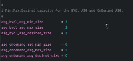
# BYOL ASG capacity
asg_byol_asg_min_size = 1
asg_byol_asg_max_size = 2
asg_byol_asg_desired_size = 1
# On-Demand (PAYG) ASG capacity
asg_ondemand_asg_min_size = 0
asg_ondemand_asg_max_size = 2
asg_ondemand_asg_desired_size = 0
Parameter Definitions
| Parameter | Description | Recommendations |
|---|
min_size | Minimum number of instances ASG maintains | Set to baseline capacity requirement |
max_size | Maximum number of instances ASG can scale to | Set based on peak traffic projections + 20% buffer |
desired_size | Target number of instances ASG attempts to maintain | Typically equals min_size for baseline capacity |
Capacity Planning Strategies
Strategy 1: BYOL Baseline with PAYG Burst (Recommended)
Objective: Optimize costs by using BYOL for steady-state traffic and PAYG for unpredictable spikes
# BYOL handles baseline 24/7 traffic
asg_byol_asg_min_size = 2
asg_byol_asg_max_size = 4
asg_byol_asg_desired_size = 2
# PAYG handles burst traffic only
asg_ondemand_asg_min_size = 0
asg_ondemand_asg_max_size = 6
asg_ondemand_asg_desired_size = 0
Scaling behavior:
- Normal operations: 2 BYOL instances handle traffic
- Traffic increases: BYOL ASG scales up to 4 instances
- Traffic continues increasing: PAYG ASG scales from 0 –> 6 instances
- Traffic decreases: PAYG ASG scales down to 0, then BYOL ASG scales down to 2
Strategy 2: All PAYG (Simplest)
Objective: Maximum flexibility with zero license management overhead
# No BYOL instances
asg_byol_asg_min_size = 0
asg_byol_asg_max_size = 0
asg_byol_asg_desired_size = 0
# All capacity is PAYG
asg_ondemand_asg_min_size = 2
asg_ondemand_asg_max_size = 8
asg_ondemand_asg_desired_size = 2
Use cases:
- Proof of concept or testing
- Short-term projects (< 6 months)
- Extreme variability where license planning is impractical
Strategy 3: All BYOL (Lowest Cost)
Objective: Minimum operating costs for long-term, predictable workloads
# All capacity is BYOL
asg_byol_asg_min_size = 2
asg_byol_asg_max_size = 6
asg_byol_asg_desired_size = 2
# No PAYG instances
asg_ondemand_asg_min_size = 0
asg_ondemand_asg_max_size = 0
asg_ondemand_asg_desired_size = 0
Requirements:
- Sufficient BYOL licenses for
max_size (6 in this example) - Predictable traffic patterns that rarely exceed max capacity
- Willingness to accept capacity ceiling (no burst beyond BYOL max)
CloudWatch Alarm Integration
Autoscale group scaling is triggered by CloudWatch alarms monitoring CPU utilization:
Default thresholds (set in underlying module):
- Scale-out alarm: CPU > 70% for 2 consecutive periods (2 minutes)
- Scale-in alarm: CPU < 30% for 2 consecutive periods (2 minutes)
Customization (requires editing underlying module):
# Located in module: fortinetdev/cloud-modules/aws
scale_out_threshold = 80 # Higher threshold = more aggressive cost optimization
scale_in_threshold = 20 # Lower threshold = more aggressive cost optimization
Capacity Planning Calculator
Formula: Capacity Needed = (Peak Gbps Throughput) / (Per-Instance Gbps) x 1.2
Example:
- Peak throughput requirement: 8 Gbps
- c6i.xlarge (4 vCPU) with IPS enabled: ~2 Gbps per instance
- Calculation: 8 / 2 x 1.2 = 4.8 –> round up to 5 instances
- Set
max_size = 5 or higher for safety margin
Important Considerations
Tip
Testing Capacity Settings
For initial deployments and testing:
- Start with min_size = 1 and max_size = 2 to verify traffic flows correctly
- Test scaling by generating load and monitoring ASG behavior
- Once validated, increase capacity to production values via AWS Console or Terraform update
- No need to destroy/recreate stack just to change capacity settings
Next Steps
After configuring capacity, proceed to Primary Scale-In Protection to protect the primary instance from being terminated during scale-in events.
Primary Scale-In Protection
Overview
Protect the primary FortiGate instance from scale-in events to maintain configuration synchronization stability and prevent unnecessary primary elections.
Configuration
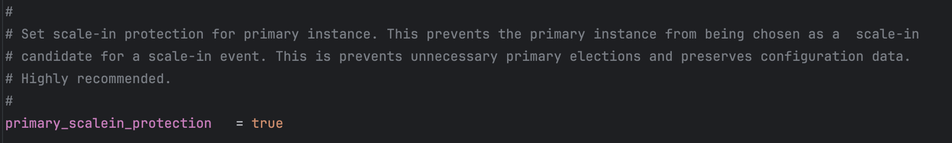
primary_scalein_protection = true
Why Protect the Primary Instance?
In FortiGate autoscale architecture:
- Primary instance: Elected leader responsible for configuration management and HA sync
- Secondary instances: Receive configuration from primary via FortiGate-native HA synchronization
Without scale-in protection:
- AWS autoscaling may select primary instance for termination during scale-in
- Remaining instances must elect new primary
- Configuration may be temporarily unavailable during election
- Potential for configuration loss if primary was processing updates
With scale-in protection:
- AWS autoscaling only terminates secondary instances
- Primary instance remains stable unless it is the last instance
- Configuration synchronization continues uninterrupted
- Predictable autoscale group behavior
How It Works
The primary_scalein_protection variable is passed through to the autoscale group configuration:
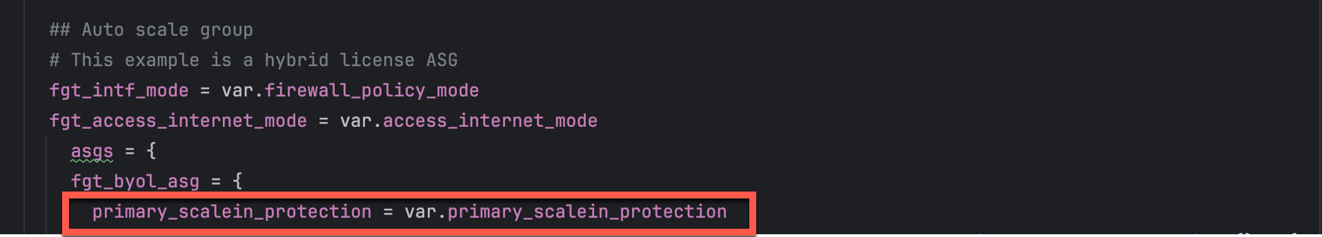
In the underlying Terraform module (autoscale_group.tf):

AWS autoscaling respects the protection attribute and never selects protected instances for scale-in events.
Verification
You can verify scale-in protection in the AWS Console:
- Navigate to EC2 > Auto Scaling Groups
- Select your autoscale group
- Click Instance management tab
- Look for Scale-in protection column showing “Protected” for primary instance
When Protection is Removed
Scale-in protection automatically removes when:
- Instance is the last remaining instance in the ASG (respecting
min_size) - Manual termination via AWS Console or API (protection can be overridden)
- Autoscale group is deleted
Best Practices
- Always enable for production: Set
primary_scalein_protection = true for production deployments - Consider disabling for dev/test: Development environments may not require protection
- Monitor primary health: Protected instances still fail health checks and can be replaced
- Document protection status: Ensure operations teams understand why primary instance is protected
AWS Documentation Reference
For more information on AWS autoscaling instance protection:
Next Steps
After configuring primary protection, review Additional Configuration Options for fine-tuning instance specifications and advanced settings.
Additional Configuration Options
Overview
This section covers additional configuration options for fine-tuning FortiGate instance specifications and advanced deployment settings.
FortiGate Instance Specifications
Instance Type Selection
fgt_instance_type = "c7gn.xlarge"
Instance type selection considerations:
- c6i/c7i series: Intel-based compute-optimized (best for x86 workloads)
- c6g/c7g/c7gn series: AWS Graviton (ARM-based, excellent performance)
- Sizing: Choose vCPU count matching expected throughput requirements
Common instance types for FortiGate:
| Instance Type | vCPUs | Memory | Network Performance | Best For |
|---|
| c6i.large | 2 | 4 GB | Up to 12.5 Gbps | Small deployments, dev/test |
| c6i.xlarge | 4 | 8 GB | Up to 12.5 Gbps | Standard production workloads |
| c6i.2xlarge | 8 | 16 GB | Up to 12.5 Gbps | High-throughput environments |
| c7gn.xlarge | 4 | 8 GB | Up to 30 Gbps | High-performance networking |
| c7gn.2xlarge | 8 | 16 GB | Up to 30 Gbps | Very high-performance networking |
FortiOS Version
fortios_version = "7.4.5"
Version specification options:
- Exact version (e.g.,
"7.4.5"): Pin to specific version for consistency across environments - Major version (e.g.,
"7.4"): Automatically use latest minor version within major release - Latest: Omit or use
"latest" to always deploy newest available version
Recommendations:
- Production: Use exact version numbers to prevent unexpected changes
- Dev/Test: Use major version or latest to test new features and fixes
- Always test new FortiOS versions in non-production before upgrading production deployments
Version considerations:
- Newer versions may include critical security fixes
- Performance improvements and new features
- Potential breaking changes in configuration syntax
- Always review release notes before upgrading
FortiGate GUI Port
Common options:
443 (default): Standard HTTPS port8443: Alternate HTTPS port (some organizations prefer moving GUI off default port for security)10443: Another common alternate port
When changing the GUI port:
- Update security group rules to allow traffic to new port
- Update documentation and runbooks with new port
- Existing sessions will be dropped when port changes
- Coordinate change with operations team
Gateway Load Balancer Cross-Zone Load Balancing
allow_cross_zone_load_balancing = true
Enabled (true) - Recommended for Production
- GWLB distributes traffic to healthy FortiGate instances in any Availability Zone
- Better utilization of capacity during partial AZ failures
- Improved overall availability and fault tolerance
- Traffic can flow to any healthy instance regardless of AZ
Disabled (false)
- GWLB only distributes traffic to instances in same AZ as GWLB endpoint
- Traffic remains within single AZ (lowest latency)
- Reduced capacity during AZ-specific health issues
- Must maintain sufficient capacity in each AZ independently
Decision Factors
Enable for:
- Production environments requiring maximum availability
- Multi-AZ deployments where instance distribution may be uneven
- Architectures where AZ-level failures must be transparent to applications
- Workloads where availability is prioritized over lowest latency
Disable for:
- Workloads with strict latency requirements
- Architectures with guaranteed even instance distribution across AZs
- Environments with predictable AZ-local traffic patterns
- Data residency requirements mandating AZ-local processing
Recommendation: Enable for production deployments to maximize availability and capacity utilization
SSH Key Pair
keypair_name = "my-fortigate-keypair"
Purpose: SSH key pair for emergency CLI access to FortiGate instances
Best practices:
- Create dedicated key pair for FortiGate instances (separate from application instances)
- Store private key securely in password manager or AWS Secrets Manager
- Rotate key pairs periodically (every 6-12 months)
- Document key pair name and location in runbooks
- Limit access to private key to authorized personnel only
Creating a key pair:
# Via AWS CLI
aws ec2 create-key-pair --key-name my-fortigate-keypair --query 'KeyMaterial' --output text > my-fortigate-keypair.pem
chmod 400 my-fortigate-keypair.pem
# Or via AWS Console: EC2 > Key Pairs > Create Key Pair
Resource Tagging
resource_tags = {
Environment = "Production"
Project = "FortiGate-Autoscale"
Owner = "security-team@example.com"
CostCenter = "CC-12345"
}
Common tags to include:
- Environment: Production, Development, Staging, Test
- Project: Project or application name
- Owner: Team or individual responsible for resources
- CostCenter: For cost allocation and chargeback
- ManagedBy: Terraform, CloudFormation, etc.
- CreatedDate: When resources were initially deployed
Benefits of comprehensive tagging:
- Cost allocation and reporting
- Resource organization and filtering
- Access control policies
- Automation and orchestration
- Compliance and governance
Summary Checklist
Before proceeding to deployment, verify you’ve configured:
- Internet Egress: EIP or NAT Gateway mode selected
- Firewall Architecture: 1-ARM or 2-ARM mode chosen
- Management Isolation: Dedicated ENI and/or VPC configured (if required)
- Licensing: BYOL directory populated or FortiFlex configured
- FortiManager: Integration enabled (if centralized management required)
- Capacity: ASG min/max/desired sizes set appropriately
- Primary Protection: Scale-in protection enabled for production
- Instance Specs: Instance type and FortiOS version selected
- Additional Options: GUI port, cross-zone LB, key pair, tags configured
Next Steps
You’re now ready to proceed to the Summary page for a complete overview of all solution components, or jump directly to Templates Overview to begin deployment.
Solution Components Summary
Overview
This summary provides a comprehensive reference of all solution components covered in this section, with quick decision guides and configuration references.
Component Quick Reference
1. Internet Egress Options
| Option | Hourly Cost | Data Processing | Monthly Cost (2 AZs) | Source IP | Best For |
|---|
| EIP Mode | $0.005/IP | None | ~$7.20 | Variable | Cost-sensitive, dev/test |
| NAT Gateway | $0.045/NAT x 2 | $0.045/GB | ~$65 base + data* | Stable | Production, compliance |
- Data processing example: 1 TB/month = $45 additional cost
Total NAT Gateway cost estimate: $65 (base) + $45 (1TB data) = $110/month for 2 AZs with 1TB egress
access_internet_mode = "eip" # or "nat_gw"
Key Decision: Do you need predictable source IPs for allowlisting (white-listing)?
- Yes –> NAT Gateway (stable IPs, higher cost)
- No –> EIP (variable IPs, lower cost)
2. Firewall Architecture
| Mode | Interfaces | Complexity | Best For |
|---|
| 2-ARM | port1 + port2 | Higher | Production, clear segmentation |
| 1-ARM | port1 only | Lower | Simplified routing |
firewall_policy_mode = "2-arm" # or "1-arm"
3. Management Isolation
Three progressive levels:
- Combined (Default): Port2 serves data + management
- Dedicated ENI: Port2 dedicated to management only
- Dedicated VPC: Complete physical network separation
enable_dedicated_management_eni = true
enable_dedicated_management_vpc = true
4. Licensing Options
| Model | Best For | Cost (12 months) | Management |
|---|
| BYOL | Long-term, predictable | Lowest | License files |
| FortiFlex | Variable, flexible | Medium | API-driven |
| PAYG | Short-term, simple | Highest | None required |
Hybrid Strategy (Recommended): BYOL baseline + PAYG burst
5. FortiManager Integration
enable_fortimanager_integration = true
fortimanager_ip = "10.0.100.50"
fortimanager_sn = "FMGVM0000000001"
Critical: FortiManager 7.6.3+ requires fgfm-allow-vm enabled before deployment
6. Autoscale Group Capacity
asg_byol_asg_min_size = 2
asg_byol_asg_max_size = 4
asg_ondemand_asg_max_size = 4
Formula: Capacity = (Peak Gbps / Per-Instance Gbps) x 1.2
7. Primary Scale-In Protection
primary_scalein_protection = true
Always enable for production to prevent primary instance termination during scale-in.
8. Additional Configuration
fgt_instance_type = "c6i.xlarge"
fortios_version = "7.4.5"
fortigate_gui_port = 443
allow_cross_zone_load_balancing = true
keypair_name = "my-fortigate-keypair"
Common Deployment Patterns
Pattern 1: Production with Maximum Isolation
access_internet_mode = "nat_gw"
firewall_policy_mode = "2-arm"
enable_dedicated_management_eni = true
enable_dedicated_management_vpc = true
asg_license_directory = "asg_license"
enable_fortimanager_integration = true
primary_scalein_protection = true
Use case: Enterprise production, compliance-driven
Pattern 2: Development and Testing
access_internet_mode = "eip"
firewall_policy_mode = "1-arm"
asg_ondemand_asg_min_size = 1
asg_ondemand_asg_max_size = 2
enable_fortimanager_integration = false
Use case: Development, testing, POC
Pattern 3: Balanced Production
access_internet_mode = "nat_gw"
firewall_policy_mode = "2-arm"
enable_dedicated_management_eni = true
fortiflex_username = "your-api-username"
enable_fortimanager_integration = true
primary_scalein_protection = true
Use case: Standard production, flexible licensing
Decision Tree
1. Do you need predictable source IPs for allowlisting?
|--- Yes --> NAT Gateway (~$110/month for 2 AZs + 1TB data)
\--- No --> EIP (~$7/month)
2. Dedicated management interface?
|--- Yes --> 2-ARM + Dedicated ENI
\--- No --> 1-ARM
3. Complete management isolation?
|--- Yes --> Dedicated Management VPC
\--- No --> Dedicated ENI or skip
4. Licensing model?
|--- Long-term (12+ months) --> BYOL
|--- Variable workload --> FortiFlex
|--- Short-term (< 3 months) --> PAYG
\--- Best optimization --> BYOL + PAYG hybrid
5. Centralized policy management?
|--- Yes --> Enable FortiManager
\--- No --> Standalone
6. Production deployment?
|--- Yes --> Enable primary scale-in protection
\--- No --> Optional
Pre-Deployment Checklist
Infrastructure:
Licensing:
FortiManager (if applicable):
Configuration:
Troubleshooting Quick Reference
| Issue | Check |
|---|
| No internet connectivity | Route tables, IGW, NAT GW, EIP |
| Management inaccessible | Security groups, routing, EIP |
| License not activating | Lambda logs, S3, DynamoDB, FortiFlex API |
| FortiManager registration fails | fgfm-allow-vm, network, serial number |
| Scaling not working | CloudWatch alarms, ASG health checks |
| Primary terminated | Verify protection enabled |
Next Steps
Proceed to Templates Overview for step-by-step deployment procedures.
Additional Resources
UI Deployment
Overview
This guide walks you through configuring the autoscale_template using the Web UI. This template deploys FortiGate autoscale groups with Gateway Load Balancer for elastic scaling.
Warning
Prerequisites:
- Deploy existing_vpc_resources first with AutoScale Deployment mode enabled
- Record the
cp, env, and tgw_name values from existing_vpc_resources outputs
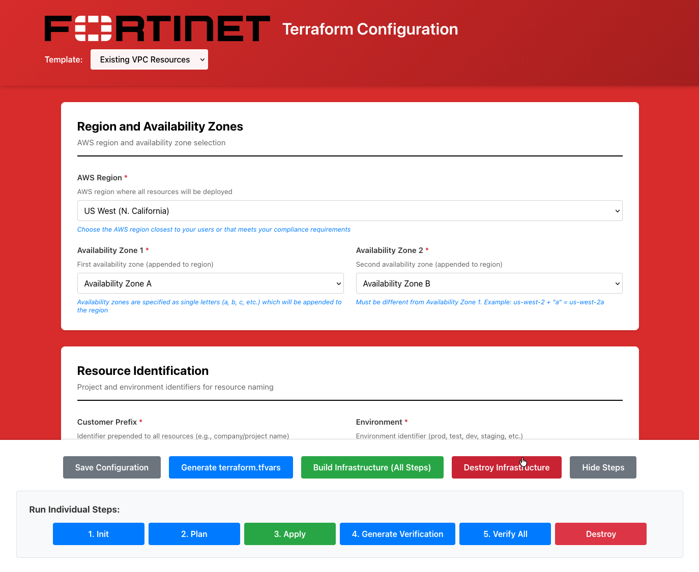
Step 1: Select Template
- Open the UI at http://localhost:3000
- In the Template dropdown at the top, select autoscale_template
- The form will load with inherited values from existing_vpc_resources
{{% notice note %}}
TODO: Add diagram - template-dropdown-autoscale
Show dropdown with “autoscale_template” selected
{{% /notice %}}
Info
Configuration Inheritance
The UI automatically inherits cp, env, aws_region, and other base settings from existing_vpc_resources. These fields will be pre-filled and shown as “Inherited from existing_vpc_resources”.
Step 2: Verify Inherited Values
Review the inherited values (shown with gray background):
- Customer Prefix (cp) - Should match existing_vpc_resources
- Environment (env) - Should match existing_vpc_resources
- AWS Region - Should match existing_vpc_resources
- Availability Zones - Should match existing_vpc_resources
Warning
Do Not Change Inherited Values
These values must match existing_vpc_resources for proper resource discovery. If they’re incorrect, fix them in existing_vpc_resources first.
{{% notice note %}}
TODO: Add diagram - inherited-fields
Show form fields with gray background indicating inherited values:
- cp: “acme” (inherited)
- env: “test” (inherited)
- aws_region: “us-west-2” (inherited)
- Note explaining these are read-only
{{% /notice %}}
Step 3: Firewall Policy Mode
Choose how FortiGate processes traffic:
1-Arm Mode (Hairpin)
- Traffic enters and exits same interface
- Simplest configuration
- Single data plane interface
2-Arm Mode (Traditional)
- Separate untrusted and trusted interfaces
- Traditional firewall model
- Better performance for high throughput
Select: 1-arm or 2-arm from dropdown
{{% notice note %}}
TODO: Add diagram - firewall-policy-mode
Show dropdown with options:
- 1-arm - Single interface (hairpin)
- 2-arm - Separate untrusted/trusted interfaces
{{% /notice %}}
Step 4: FortiGate Configuration
Instance Type
- Select FortiGate Instance Type from dropdown:
- c5n.xlarge - 4 vCPU / 10.5GB RAM (minimum)
- c5n.2xlarge - 8 vCPU / 21GB RAM
- c5n.4xlarge - 16 vCPU / 42GB RAM
- c5n.9xlarge - 36 vCPU / 96GB RAM
FortiOS Version
- Enter FortiOS Version (e.g.,
7.4.5 or 7.6)
Admin Password
- Enter FortiGate Admin Password
- Minimum 8 characters
- Used to login to FortiGate instances
{{% notice note %}}
TODO: Add diagram - fortigate-config
Show:
- Instance Type dropdown: “c5n.xlarge” selected
- FortiOS Version field: “7.4.5”
- Admin Password field: [password masked]
{{% /notice %}}
Step 5: Autoscale Group Settings
Desired Capacity
- Enter Desired Capacity - Number of FortiGates to maintain (default: 2)
Minimum Size
- Enter Minimum Size - Minimum FortiGates in group (default: 2)
Maximum Size
- Enter Maximum Size - Maximum FortiGates in group (default: 6)
Scale-In Protection
- Check Enable Scale-In Protection to prevent automatic instance termination
{{% notice note %}}
TODO: Add diagram - autoscale-settings
Show:
- Desired Capacity: 2
- Minimum Size: 2
- Maximum Size: 6
- Scale-In Protection checkbox
{{% /notice %}}
Tip
Autoscaling Recommendations
- Start with desired capacity = 2 for testing
- Set maximum based on expected peak load
- Enable scale-in protection during initial testing
Step 6: Licensing Configuration
Choose ONE licensing mode:
PAYG (Pay-As-You-Go)
- Select License Type:
payg - No additional fields required
- AWS Marketplace billing applies
BYOL (Bring Your Own License)
- Select License Type:
byol - Upload license files to
terraform/aws/autoscale_template/asg_license/:cp license1.lic terraform/aws/autoscale_template/asg_license/
cp license2.lic terraform/aws/autoscale_template/asg_license/
# Add as many licenses as your maximum ASG size
- Lambda will apply licenses automatically on instance launch
FortiFlex
- Select License Type:
fortiflex - Enter FortiFlex Token
- Lambda retrieves licenses from FortiFlex automatically
{{% notice note %}}
TODO: Add diagram - licensing
Show:
- License Type dropdown with three options: payg, byol, fortiflex
- FortiFlex Token field (visible when fortiflex selected)
- Help text explaining each licensing mode
{{% /notice %}}
Step 7: Transit Gateway Integration (Optional)
If you enabled Transit Gateway in existing_vpc_resources:
Enable TGW Attachment
- Check Enable Transit Gateway Attachment
- Enter Transit Gateway Name from existing_vpc_resources outputs
- Example:
acme-test-tgw - Find with:
terraform output tgw_name
{{% notice note %}}
TODO: Add diagram - tgw-integration
Show:
- Enable TGW Attachment checkbox [[x]]
- Transit Gateway Name field: “acme-test-tgw”
- Help text: “Use ’tgw_name’ from existing_vpc_resources outputs”
{{% /notice %}}
Info
TGW Routing
When enabled, the template automatically:
- Creates TGW attachment for inspection VPC
- Updates spoke VPC route tables to point to inspection VPC
- Enables east-west and north-south traffic inspection
Step 8: Distributed Inspection (Optional)
If you want GWLB endpoints in distributed spoke VPCs:
- Check Enable Distributed Inspection
- The template will discover VPCs tagged with your
cp and env values - GWLB endpoints will be created in discovered VPCs
{{% notice note %}}
TODO: Add diagram - distributed-inspection
Show:
- Enable Distributed Inspection checkbox
- Help text explaining bump-in-the-wire inspection
- Diagram: VPC –> GWLBe –> GWLB –> GENEVE –> FortiGate
{{% /notice %}}
Info
Distributed vs Centralized
- Centralized (TGW): Traffic flows through TGW to inspection VPC
- Distributed: GWLB endpoints placed directly in spoke VPCs
- Both can be enabled simultaneously
Step 9: Internet Access Mode
Choose how FortiGates access the internet:
EIP Mode (Default)
- Select Access Internet Mode:
eip - Each FortiGate gets an Elastic IP
- Distributed egress from each instance
NAT Gateway Mode
- Select Access Internet Mode:
nat_gw - Centralized egress through NAT Gateways
- Requires NAT Gateways in inspection VPC
{{% notice note %}}
TODO: Add diagram - internet-access
Show dropdown with options:
- eip - Elastic IP per instance (distributed egress)
- nat_gw - NAT Gateway (centralized egress)
{{% /notice %}}
Step 10: Management Configuration
Choose management access mode:
Standard Management (Default)
- Management via data plane interfaces
- No additional ENIs required
- Simplest configuration
Dedicated Management ENI
- Check Enable Dedicated Management ENI
- Converts port2 to dedicated management interface (instead of data plane)
- Better security isolation
Dedicated Management VPC
- Check Enable Dedicated Management VPC
- Management interfaces in separate management VPC
- Requires existing_vpc_resources with management VPC enabled
- Maximum security isolation
{{% notice note %}}
TODO: Add diagram - management-config
Show:
- Enable Dedicated Management ENI checkbox
- Enable Dedicated Management VPC checkbox
- Help text explaining security isolation
{{% /notice %}}
Step 11: FortiManager Integration (Optional)
If you deployed FortiManager in existing_vpc_resources:
- Check Enable FortiManager
- Enter FortiManager IP from existing_vpc_resources outputs
- Example:
10.3.0.10 - Find with:
terraform output fortimanager_private_ip
- Enter FortiManager Serial Number
- Login to FortiManager CLI:
get system status
{{% notice note %}}
TODO: Add diagram - fortimanager-integration
Show:
- Enable FortiManager checkbox [[x]]
- FortiManager IP field: “10.3.0.10”
- Serial Number field
- Help text: “Get from existing_vpc_resources outputs”
{{% /notice %}}
Info
FortiManager Registration
When enabled:
- FortiGate instances automatically register with FortiManager on launch
- Lambda handles authorization
- ADOM configuration optional
Step 12: FortiAnalyzer Integration (Optional)
If you deployed FortiAnalyzer in existing_vpc_resources:
- Check Enable FortiAnalyzer
- Enter FortiAnalyzer IP from existing_vpc_resources outputs
- Example:
10.3.0.11 - Find with:
terraform output fortianalyzer_private_ip
{{% notice note %}}
TODO: Add diagram - fortianalyzer-integration
Show:
- Enable FortiAnalyzer checkbox [[x]]
- FortiAnalyzer IP field: “10.3.0.11”
{{% /notice %}}
Step 13: Security Configuration
EC2 Key Pair
- Select Key Pair from dropdown (should match existing_vpc_resources)
Management CIDR
- Management CIDR list is inherited from existing_vpc_resources
- Shows list of allowed IP ranges for SSH/HTTPS access
- Cannot be modified here (inherited)
{{% notice note %}}
TODO: Add diagram - security-config-autoscale
Show:
- Key Pair dropdown: “my-keypair” (inherited)
- Management CIDR list field: [“203.0.113.10/32”] (inherited, read-only)
{{% /notice %}}
Step 14: Save Configuration
- Click the Save Configuration button
- Confirmation: “Configuration saved successfully!”
{{% notice note %}}
TODO: Add diagram - save-autoscale
Show Save Configuration button with success message
{{% /notice %}}
- Click Generate terraform.tfvars
- Review the generated configuration in preview window
- Verify all settings are correct
{{% notice note %}}
TODO: Add diagram - generated-preview-autoscale
Show preview window with generated terraform.tfvars content
{{% /notice %}}
Step 16: Download or Save to Template
Option A: Download
- Click Download
- File saves as
autoscale_template.tfvars - Copy to terraform directory:
cp ~/Downloads/autoscale_template.tfvars \
terraform/aws/autoscale_template/terraform.tfvars
Option B: Save Directly
- Click Save to Template
- Confirmation: “terraform.tfvars saved to: terraform/aws/autoscale_template/terraform.tfvars”
cd terraform/aws/autoscale_template
# Initialize Terraform
terraform init
# Review execution plan
terraform plan
# Deploy infrastructure
terraform apply
Type yes when prompted.
Expected deployment time: 15-20 minutes
Common Configuration Patterns
Pattern 1: Simple Autoscale with TGW
Firewall Policy Mode: 1-arm
License Type: payg
[x] Enable Transit Gateway Attachment
[ ] Enable Distributed Inspection
[ ] Enable Dedicated Management ENI
[ ] Enable FortiManager
Desired Capacity: 2
Minimum Size: 2
Maximum Size: 4
Use case: Basic autoscaling with centralized inspection via TGW
Pattern 2: Distributed Inspection
Firewall Policy Mode: 2-arm
License Type: byol
[ ] Enable Transit Gateway Attachment
[x] Enable Distributed Inspection
[ ] Enable Dedicated Management ENI
[ ] Enable FortiManager
Desired Capacity: 2
Minimum Size: 2
Maximum Size: 6
Use case: Bump-in-the-wire inspection in distributed spoke VPCs
Pattern 3: Full Management with FortiManager
Firewall Policy Mode: 2-arm
License Type: payg
[x] Enable Transit Gateway Attachment
[ ] Enable Distributed Inspection
[x] Enable Dedicated Management VPC
[x] Enable FortiManager
[x] Enable FortiAnalyzer
Desired Capacity: 2
Minimum Size: 2
Maximum Size: 6
Use case: Production-like environment with centralized management
Validation and Errors
The UI validates:
- FortiGate admin password minimum length (8 characters)
- Autoscale group sizes (min <= desired <= max)
- FortiManager IP format
- Transit Gateway name format
- All required fields filled
{{% notice note %}}
TODO: Add diagram - validation-errors-autoscale
Show form with validation errors highlighted
{{% /notice %}}
Next Steps
After deploying autoscale_template:
Verify deployment:
Access FortiGate:
- Get load balancer DNS from outputs
- GUI:
https://<load-balancer-dns> - Username:
admin - Password:
<fortigate_asg_password>
Test traffic flow:
- From spoke VPC instances, test internet connectivity
- Verify traffic appears in FortiGate logs
- Test east-west traffic between spoke VPCs
Monitor autoscaling:
- Check CloudWatch metrics
- Review Lambda logs
- Monitor ASG activity
Troubleshooting
FortiGates Not Joining FortiManager
Check:
- FortiManager IP is correct
- FortiManager serial number is correct
- Security groups allow traffic between inspection VPC and management VPC
- FortiManager has
fgfm-allow-vm enable set
License Application Failed
Check:
- License files are in
asg_license/ directory - Sufficient licenses for maximum ASG size
- FortiFlex token is valid (if using FortiFlex)
- Lambda logs for error messages
No Traffic Flowing Through FortiGates
Check:
- TGW route tables point to inspection VPC attachment
- Security groups allow traffic on FortiGate interfaces
- FortiGate firewall policies exist and allow traffic
- Gateway Load Balancer health checks passing
Deployment Guide
Step-by-Step Deployment
Prerequisites
- AWS account with appropriate permissions
- Terraform 1.0 or later installed
- AWS CLI configured with credentials
- SSH keypair created in target AWS region
- FortiGate licenses (if using BYOL) or FortiFlex account (if using FortiFlex)
existing_vpc_resources deployed (if using lab environment)
Step 1: Navigate to Template Directory
cd fortinet-ui-terraform/terraform/aws/autoscale_template
cp terraform.tfvars.example terraform.tfvars
Region and Availability Zones

aws_region         = "us-west-2"
availability_zone_1 = "a"
availability_zone_2 = "c"
Warning
Variable Coordination
If you deployed existing_vpc_resources, these values MUST MATCH exactly:
aws_regionavailability_zone_1availability_zone_2cp (customer prefix)env (environment)
Mismatched values will cause resource discovery failures and deployment errors.
Customer Prefix and Environment

cp  = "acme"    # Customer prefix
env = "test"    # Environment: prod, test, dev

keypair = "my-aws-keypair" # Must exist in target region
my_ip = "203.0.113.10/32" # Your public IP for management access
fortigate_asg_password = "SecurePassword123!" # Admin password for FortiGates
Warning
Password Requirements
The fortigate_asg_password must meet FortiOS password requirements:
- Minimum 8 characters
- At least one uppercase letter
- At least one lowercase letter
- At least one number
- No special characters that might cause shell escaping issues
Never commit passwords to version control. Consider using:
- Terraform variables marked as sensitive
- Environment variables:
TF_VAR_fortigate_asg_password - AWS Secrets Manager
- HashiCorp Vault

To connect to Transit Gateway:
enable_tgw_attachment = true

Specify TGW name:
# If using existing_vpc_resources template
attach_to_tgw_name = "acme-test-tgw" # Matches existing_vpc_resources output
# If using existing production TGW
attach_to_tgw_name = "production-tgw" # Your production TGW name
Tip
Finding Your Transit Gateway Name
If you don’t know your TGW name:
aws ec2 describe-transit-gateways \
--query 'TransitGateways[*].[Tags[?Key==`Name`].Value | [0], TransitGatewayId]' \
--output table
The attach_to_tgw_name should match the Name tag of your Transit Gateway.
To skip TGW attachment (distributed architecture):
enable_tgw_attachment = false
East-West Inspection (requires TGW attachment):
enable_east_west_inspection = true # Routes spoke-to-spoke traffic through FortiGate
Firewall Mode
firewall_policy_mode = "2-arm" # or "1-arm"
Recommendations:
- 2-arm: Recommended for most deployments (better throughput)
- 1-arm: Use when simplified routing is required
See Firewall Architecture for detailed comparison.
Internet Egress Mode
access_internet_mode = "nat_gw" # or "eip"
Recommendations:
- nat_gw: Production deployments (higher availability)
- eip: Lower cost, simpler architecture
See Internet Egress for detailed comparison.
Dedicated Management ENI
enable_dedicated_management_eni = true
Separates management traffic from data plane. Recommended for production.
Dedicated Management VPC
enable_dedicated_management_vpc = true
# If using existing_vpc_resources with default tags:
dedicated_management_vpc_tag = "acme-test-management-vpc"
dedicated_management_public_az1_subnet_tag = "acme-test-management-public-az1-subnet"
dedicated_management_public_az2_subnet_tag = "acme-test-management-public-az2-subnet"
# If using existing management VPC with custom tags:
dedicated_management_vpc_tag = "my-custom-mgmt-vpc-tag"
dedicated_management_public_az1_subnet_tag = "my-custom-mgmt-az1-tag"
dedicated_management_public_az2_subnet_tag = "my-custom-mgmt-az2-tag"
See Management Isolation for options and recommendations.
Info
Automatic Implication
When enable_dedicated_management_vpc = true, the template automatically sets enable_dedicated_management_eni = true. You don’t need to configure both explicitly.

The template supports three licensing models. Choose one or combine them for hybrid licensing.
Option 1: BYOL (Bring Your Own License)
asg_license_directory = "asg_license" # Directory containing .lic files
Prerequisites:
Create the license directory:
Place license files in the directory:
terraform/aws/autoscale_template/
|---- terraform.tfvars
|---- asg_license/
| |---- FGVM01-001.lic
| |---- FGVM01-002.lic
| |---- FGVM01-003.lic
| \---- FGVM01-004.lic
Ensure you have at least as many licenses as asg_byol_asg_max_size
Warning
License Pool Exhaustion
If you run out of BYOL licenses:
- New BYOL instances launch but remain unlicensed
- Unlicensed instances operate at 1 Mbps throughput
- FortiGuard services will not activate
- If on-demand ASG is configured, scaling continues using PAYG instances
Recommended: Provision 20% more licenses than asg_byol_asg_max_size
Option 2: FortiFlex (API-Driven)
fortiflex_username = "xxxxxxxx-xxxx-xxxx-xxxx-xxxxxxxxxxxx" # API username (UUID)
fortiflex_password = "xxxxxxxxxxxxxxxxxxxxx" # API password
fortiflex_sn_list = ["FGVMELTMxxxxxxxx"] # Optional: specific program serial numbers
fortiflex_configid_list = ["My_4CPU_Config"] # Configuration names (must match CPU count)
Prerequisites:
- Register FortiFlex program via FortiCare
- Purchase point packs
- Create configurations matching your instance types
- Generate API credentials via IAM portal
CPU count matching:
fgt_instance_type = "c6i.xlarge" # 4 vCPUs
fortiflex_configid_list = ["My_4CPU_Config"] # MUST have 4 CPUs configured
Warning
Security Best Practice
Never commit FortiFlex credentials to version control. Use:
- Terraform Cloud sensitive variables
- AWS Secrets Manager
- Environment variables:
TF_VAR_fortiflex_username and TF_VAR_fortiflex_password - HashiCorp Vault
Example using environment variables:
export TF_VAR_fortiflex_username="xxxxxxxx-xxxx-xxxx-xxxx-xxxxxxxxxxxx"
export TF_VAR_fortiflex_password="xxxxxxxxxxxxxxxxxxxxx"
terraform apply
See FortiFlex Setup Guide for complete configuration details.
Option 3: PAYG (AWS Marketplace)
# No explicit configuration needed
# Just set on-demand ASG capacities
asg_byol_asg_min_size = 0
asg_byol_asg_max_size = 0
asg_ondemand_asg_min_size = 2
asg_ondemand_asg_max_size = 8
Prerequisites:
- Accept FortiGate-VM terms in AWS Marketplace
- No license files or API credentials required
- Licensing cost included in hourly EC2 charge
Hybrid Licensing (Recommended for Production)
Combine licensing models for cost optimization:
# BYOL for baseline capacity (lowest cost)
asg_license_directory = "asg_license"
asg_byol_asg_min_size = 2
asg_byol_asg_max_size = 4
# PAYG for burst capacity (highest flexibility)
asg_ondemand_asg_min_size = 0
asg_ondemand_asg_max_size = 4
See Licensing Options for detailed comparison and cost analysis.
# BYOL ASG
asg_byol_asg_min_size = 2
asg_byol_asg_max_size = 4
asg_byol_asg_desired_size = 2
# On-Demand ASG
asg_ondemand_asg_min_size = 0
asg_ondemand_asg_max_size = 4
asg_ondemand_asg_desired_size = 0
# Primary scale-in protection
primary_scalein_protection = true
Capacity planning guidance:
| Deployment Type | Recommended Configuration |
|---|
| Development/Test | min=1, max=2, desired=1 |
| Small Production | min=2, max=4, desired=2 |
| Medium Production | min=2, max=8, desired=4 |
| Large Production | min=4, max=16, desired=6 |
Scaling behavior:
- BYOL instances scale first (up to
asg_byol_asg_max_size) - On-demand instances scale when BYOL capacity exhausted
- CloudWatch alarms trigger scale-out at 80% CPU (default)
- Scale-in occurs at 30% CPU (default)
See Autoscale Group Capacity for detailed planning.
fgt_instance_type = "c7gn.xlarge"
fortios_version = "7.4.5"
fortigate_gui_port = 443
Instance type recommendations:
| Use Case | Recommended Type | vCPUs | Network Performance |
|---|
| Testing/Lab | t3.xlarge | 4 | Up to 5 Gbps |
| Small Production | c6i.xlarge | 4 | Up to 12.5 Gbps |
| Medium Production | c6i.2xlarge | 8 | Up to 12.5 Gbps |
| High Performance | c7gn.xlarge | 4 | Up to 25 Gbps |
| Very High Performance | c7gn.4xlarge | 16 | 50 Gbps |
FortiOS version selection:
- Use latest stable release for new deployments
- Test new versions in dev/test before production
- Check FortiOS Release Notes for compatibility
enable_fortimanager_integration = true
fortimanager_ip = "10.3.0.10" # FortiManager IP
fortimanager_sn = "FMGVM0000000001" # FortiManager serial number
fortimanager_vrf_select = 1 # VRF for management routing
Warning
FortiManager 7.6.3+ Configuration Required
If using FortiManager 7.6.3 or later, you must enable VM device recognition before deploying:
On FortiManager CLI:
config system global
    set fgfm-allow-vm enable
end
Verify the setting:
show system global | grep fgfm-allow-vm
Without this configuration, FortiGate-VM instances will fail to register with FortiManager.
See FortiManager Integration for complete details.
FortiManager integration behavior:
- Lambda generates
config system central-management on primary FortiGate only - Primary FortiGate registers with FortiManager as unauthorized device
- VDOM exception prevents sync to secondary instances
- Configuration syncs from FortiManager –> Primary –> Secondaries
See FortiManager Integration Configuration for advanced options including UMS mode.
vpc_cidr_inspection = "10.0.0.0/16"
vpc_cidr_management = "10.3.0.0/16" # Must match existing_vpc_resources if used
vpc_cidr_spoke = "192.168.0.0/16" # Supernet for all spoke VPCs
vpc_cidr_east = "192.168.0.0/24"
vpc_cidr_west = "192.168.1.0/24"
subnet_bits = 8 # /16 + 8 = /24 subnets
Warning
CIDR Planning Considerations
Ensure:
- No overlap with existing networks
- Management VPC CIDR matches
existing_vpc_resources if used - Spoke supernet encompasses all individual spoke VPC CIDRs
- Sufficient address space for growth
- Alignment with corporate IP addressing standards
Common mistakes:
- Overlapping inspection VPC with management VPC
- Spoke CIDR too small for number of VPCs
- Mismatched CIDRs between templates
endpoint_name_az1 = "asg-gwlbe_az1"
endpoint_name_az2 = "asg-gwlbe_az2"
These names are used for route table lookups when configuring TGW routing or spoke VPC routing.
FortiGate System Autoscale
enable_fgt_system_autoscale = true
Enables FortiGate-native HA synchronization between instances. Recommended to leave enabled.
CloudWatch Alarms
# Scale-out threshold (default: 80% CPU)
scale_out_threshold = 80
# Scale-in threshold (default: 30% CPU)
scale_in_threshold = 30
Adjust based on your traffic patterns and capacity requirements.
Step 15: Review Complete Configuration
Review your complete terraform.tfvars file before deployment. Here’s a complete example:
Click to expand complete example terraform.tfvars
#-----------------------------------------------------------------------
# Core Configuration
#-----------------------------------------------------------------------
aws_region = "us-west-2"
availability_zone_1 = "a"
availability_zone_2 = "c"
cp = "acme"
env = "prod"
#-----------------------------------------------------------------------
# Security
#-----------------------------------------------------------------------
keypair = "acme-keypair"
my_ip = "203.0.113.10/32"
fortigate_asg_password = "SecurePassword123!"
#-----------------------------------------------------------------------
# Transit Gateway
#-----------------------------------------------------------------------
enable_tgw_attachment = true
attach_to_tgw_name = "acme-prod-tgw"
enable_east_west_inspection = true
#-----------------------------------------------------------------------
# Architecture Options
#-----------------------------------------------------------------------
firewall_policy_mode = "2-arm"
access_internet_mode = "nat_gw"
#-----------------------------------------------------------------------
# Management Options
#-----------------------------------------------------------------------
enable_dedicated_management_eni = true
enable_dedicated_management_vpc = true
dedicated_management_vpc_tag = "acme-prod-management-vpc"
dedicated_management_public_az1_subnet_tag = "acme-prod-management-public-az1-subnet"
dedicated_management_public_az2_subnet_tag = "acme-prod-management-public-az2-subnet"
#-----------------------------------------------------------------------
# FortiManager Integration
#-----------------------------------------------------------------------
enable_fortimanager_integration = true
fortimanager_ip = "10.3.0.10"
fortimanager_sn = "FMGVM0000000001"
fortimanager_vrf_select = 1
#-----------------------------------------------------------------------
# Licensing - Hybrid BYOL + PAYG
#-----------------------------------------------------------------------
asg_license_directory = "asg_license"
#-----------------------------------------------------------------------
# Autoscale Group Capacity
#-----------------------------------------------------------------------
# BYOL baseline
asg_byol_asg_min_size = 2
asg_byol_asg_max_size = 4
asg_byol_asg_desired_size = 2
# PAYG burst
asg_ondemand_asg_min_size = 0
asg_ondemand_asg_max_size = 4
asg_ondemand_asg_desired_size = 0
# Scale-in protection
primary_scalein_protection = true
#-----------------------------------------------------------------------
# FortiGate Specifications
#-----------------------------------------------------------------------
fgt_instance_type = "c6i.xlarge"
fortios_version = "7.4.5"
fortigate_gui_port = 443
enable_fgt_system_autoscale = true
#-----------------------------------------------------------------------
# Network CIDRs
#-----------------------------------------------------------------------
vpc_cidr_inspection = "10.0.0.0/16"
vpc_cidr_management = "10.3.0.0/16"
vpc_cidr_spoke = "192.168.0.0/16"
vpc_cidr_east = "192.168.0.0/24"
vpc_cidr_west = "192.168.1.0/24"
subnet_bits = 8
#-----------------------------------------------------------------------
# GWLB Endpoints
#-----------------------------------------------------------------------
endpoint_name_az1 = "acme-prod-gwlbe-az1"
endpoint_name_az2 = "acme-prod-gwlbe-az2"
Step 16: Deploy the Template
Initialize Terraform:
Review the execution plan:
Expected output will show ~40-60 resources to be created.
Deploy the infrastructure:
Type yes when prompted.
Expected deployment time: 15-20 minutes
Deployment progress indicators:
- VPC and networking: ~2 minutes
- Security groups and IAM: ~1 minute
- Lambda functions and DynamoDB: ~2 minutes
- GWLB and endpoints: ~5 minutes
- FortiGate instances launching: ~5-10 minutes
Step 17: Monitor Deployment
Watch CloudWatch logs for Lambda execution:
# Get Lambda function name from Terraform
terraform output lambda_function_name

# Stream logs
aws logs tail /aws/lambda/<function-name> --follow
Watch Auto Scaling Group activity:
# Get ASG name
aws autoscaling describe-auto-scaling-groups \
  --query 'AutoScalingGroups[?contains(AutoScalingGroupName, `acme-prod`)].AutoScalingGroupName'

# Watch instance launches
aws autoscaling describe-scaling-activities \
  --auto-scaling-group-name <asg-name> \
  --max-records 10
Step 18: Verify Deployment
Check FortiGate Instances
# List running FortiGate instances
aws ec2 describe-instances \
  --filters "Name=tag:cp,Values=acme" \
           "Name=tag:env,Values=prod" \
           "Name=instance-state-name,Values=running" \
  --query 'Reservations[*].Instances[*].[InstanceId,PublicIpAddress,Tags[?Key==`Name`].Value|[0]]' \
  --output table
Access FortiGate GUI
# Get FortiGate public IP
terraform output fortigate_instance_ips

# Access GUI
open https://<fortigate-public-ip>:443
Login credentials:
- Username:
admin - Password: Value from
fortigate_asg_password variable
Verify License Assignment
For BYOL:
# SSH to FortiGate
ssh -i ~/.ssh/keypair.pem admin@<fortigate-ip>

# Check license status
get system status

# Look for:
# Serial-Number: FGVMxxxxxxxxxx (not FGVMEVXXXXXXXXX)
# License Status: Valid
For FortiFlex:
- Check Lambda CloudWatch logs for successful API calls
- Verify entitlements created in FortiFlex portal
- Check FortiGate shows licensed status
For PAYG:
- Instances automatically licensed via AWS
- Verify license status in FortiGate GUI
Verify Transit Gateway Attachment
aws ec2 describe-transit-gateway-attachments \
  --filters "Name=state,Values=available" \
           "Name=resource-type,Values=vpc" \
  --query 'TransitGatewayAttachments[?contains(Tags[?Key==`Name`].Value|[0], `inspection`)]'
Verify FortiManager Registration
If FortiManager integration enabled:
- Access FortiManager GUI:
https://<fortimanager-ip> - Navigate to Device Manager > Device & Groups
- Look for unauthorized device with serial number matching primary FortiGate
- Right-click device and select Authorize
Test Traffic Flow
From jump box (if using existing_vpc_resources):
# SSH to jump box
ssh -i ~/.ssh/keypair.pem ec2-user@<jump-box-ip>

# Test internet connectivity (should go through FortiGate)
curl https://www.google.com

# Test spoke VPC connectivity
curl http://<linux-instance-ip>
On FortiGate:
# SSH to FortiGate
ssh -i ~/.ssh/keypair.pem admin@<fortigate-ip>

# Monitor real-time traffic
diagnose sniffer packet any 'host 192.168.0.50' 4

# Check firewall policies
get firewall policy

# View active sessions
diagnose sys session list
Reference
Outputs Reference
Important outputs from the template:
| Output | Description | Use Case |
|---|
inspection_vpc_id | ID of inspection VPC | VPC peering, routing configuration |
inspection_vpc_cidr | CIDR of inspection VPC | Route table configuration |
gwlb_arn | Gateway Load Balancer ARN | GWLB endpoint creation |
gwlb_endpoint_az1_id | GWLB endpoint ID in AZ1 | Spoke VPC route tables |
gwlb_endpoint_az2_id | GWLB endpoint ID in AZ2 | Spoke VPC route tables |
fortigate_autoscale_group_name | BYOL ASG name | CloudWatch, monitoring |
fortigate_ondemand_autoscale_group_name | PAYG ASG name | CloudWatch, monitoring |
lambda_function_name | Lifecycle Lambda function name | CloudWatch logs, debugging |
dynamodb_table_name | License tracking table name | License management |
s3_bucket_name | License storage bucket name | License management |
tgw_attachment_id | TGW attachment ID | TGW routing configuration |
Best Practices
Pre-Deployment
- Plan capacity thoroughly: Use Autoscale Group Capacity guidance
- Test in dev/test first: Validate configuration before production
- Document customizations: Maintain runbook of configuration decisions
- Review security groups: Ensure least-privilege access
- Coordinate with network team: Verify CIDR allocations don’t conflict
During Deployment
- Monitor Lambda logs: Watch for errors during instance launch
- Verify license assignments: Check first instance gets licensed before scaling
- Test connectivity incrementally: Validate routing at each step
- Document public IPs: Save instance IPs for troubleshooting access
Post-Deployment
- Configure firewall policies immediately: Don’t leave FortiGates in pass-through mode
- Enable security profiles: IPS, Application Control, Web Filtering
- Set up monitoring: CloudWatch alarms, FortiGate logging
- Test failover scenarios: Verify autoscaling behavior
- Document recovery procedures: Maintain runbook for common issues
Ongoing Operations
- Monitor autoscale events: Review CloudWatch metrics weekly
- Update FortiOS regularly: Test updates in dev first
- Review firewall logs: Look for blocked traffic patterns
- Optimize scaling thresholds: Adjust based on observed traffic
- Plan capacity additions: Add licenses/entitlements before needed
Cleanup
Destroying the Deployment
To destroy the autoscale_template infrastructure:
cd terraform/aws/autoscale_template
terraform destroy
Type yes when prompted.
Warning
Destroy Order is Critical
If you also deployed existing_vpc_resources, destroy in this order:
- First: Destroy
autoscale_template (this template) - Second: Destroy
existing_vpc_resources
Why? The inspection VPC has a Transit Gateway attachment to the TGW created by existing_vpc_resources. Destroying the TGW first will cause the attachment deletion to fail.
# Correct order:
cd terraform/aws/autoscale_template
terraform destroy
cd ../existing_vpc_resources
terraform destroy
Selective Cleanup
To destroy only specific components:
# Destroy only BYOL ASG
terraform destroy -target=module.fortigate_byol_asg
# Destroy only on-demand ASG
terraform destroy -target=module.fortigate_ondemand_asg
# Destroy only Lambda and DynamoDB
terraform destroy -target=module.lambda_functions
terraform destroy -target=module.dynamodb_table
Verify Complete Cleanup
After destroying, verify no resources remain:
# Check VPCs
aws ec2 describe-vpcs --filters "Name=tag:cp,Values=acme" "Name=tag:env,Values=prod"
# Check running instances
aws ec2 describe-instances \
--filters "Name=instance-state-name,Values=running" \
"Name=tag:cp,Values=acme"
# Check GWLB
aws elbv2 describe-load-balancers \
--query 'LoadBalancers[?contains(LoadBalancerName, `acme`)]'
# Check Lambda functions
aws lambda list-functions --query 'Functions[?contains(FunctionName, `acme`)]'
Summary
The autoscale_template is the core component of the FortiGate Autoscale Simplified Template, providing:
Complete autoscale infrastructure: FortiGate ASG, GWLB, Lambda, IAM
Flexible deployment options: Centralized, distributed, or hybrid architectures
Multiple licensing models: BYOL, FortiFlex, PAYG, or hybrid
Management options: Dedicated ENI, dedicated VPC, FortiManager integration
Production-ready: High availability, autoscaling, lifecycle management
Next Steps:
Document Version: 1.0
Last Updated: November 2025
Terraform Module Version: Compatible with terraform-aws-cloud-modules v1.0+