GCP Advanced Routing with Network Connectivity Center

This site will discuss how Google Cloud Platform (GCP) uses Network Connectivity Center (NCC) to provide dynamic routing. Specifically, FortiGate will serve as a Networked Virtual Appliance (NVA) to provide routing and security between VPCs in CGP, as well as provide inter-regional HA. Students will use a virtual lab created in Qwiklabs. Each student will have their own project and resources. This lab is allocated for 90 minutes. However, the timer is set for 120 minutes in order to give students a bit of extra time, if needed.

Learning Objectives

  • Configure GCP NCC Hub and Spoke Architecture
  • Configure FortiGate BGP peering with GCP NCC spokes
  • Configure FortiGate overlay IPSec and BGP Peering between “gcp” and “remote” devices.
  • Configure FortiGate Firewall Policy to allow and inspect traffic

Concept

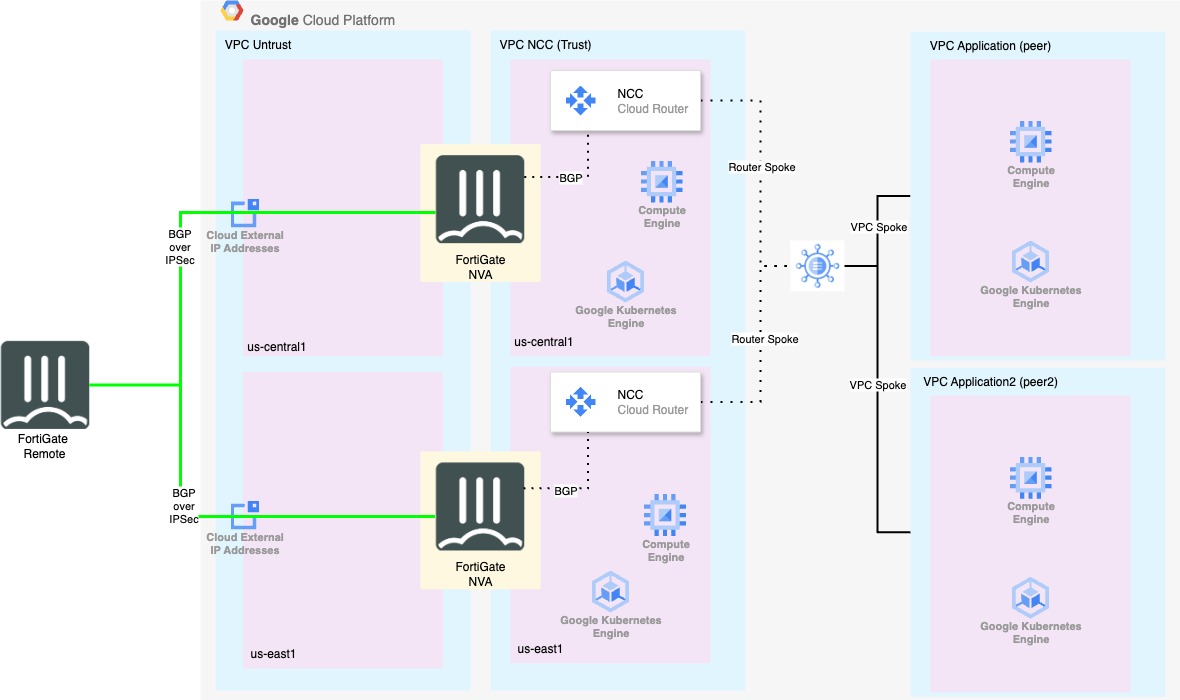
The below diagram shows the (High Level) architecture we are building for the lab. The remote FortiGate is represented as a VM, because the whole envrionment is built in GCP, but this could just as easily be an on-prem physical FortiGate or even FortiSASE.

NCC High Level NCC High Level

Version:
Last updated: Mon, Jul 14, 2025 20:09:01 UTC
Copyright© 2025 Fortinet, Inc. All rights reserved. Fortinet®, FortiGate®, FortiCare® and FortiGuard®, and certain other marks are registered trademarks of Fortinet, Inc., and other Fortinet names herein may also be registered and/or common law trademarks of Fortinet. All other product or company names may be trademarks of their respective owners. Performance and other metrics contained herein were attained in internal lab tests under ideal conditions, and actual performance and other results may vary. Network variables, different network environments and other conditions may affect performance results. Nothing herein represents any binding commitment by Fortinet, and Fortinet disclaims all warranties, whether express or implied, except to the extent Fortinet enters a binding written contract, signed by Fortinet’s General Counsel, with a purchaser that expressly warrants that the identified product will perform according to certain expressly-identified performance metrics and, in such event, only the specific performance metrics expressly identified in such binding written contract shall be binding on Fortinet. For absolute clarity, any such warranty will be limited to performance in the same ideal conditions as in Fortinet’s internal lab tests. Fortinet disclaims in full any covenants, representations, and guarantees pursuant hereto, whether express or implied. Fortinet reserves the right to change, modify, transfer, or otherwise revise this publication without notice, and the most current version of the publication shall be applicable.

Subsections of NCC Advanced Routing

Getting Started with Qwiklabs

GoalLog into Qwiklab
TaskCreate account and login
Verify task completionYou should see lab card available on your home page

This lab will use Qwiklabs to build all of the required infrastructure.

If you already have an account, click this link to sign in using the same email address that you used to register for this course. You will see a link to the lab session on your Dashboard.

If you do not have an account, click on this link and create one using the same email that you used to register for this course.

Create Account Create Account

Go To Lab

Once you have verified your account, log in and you will see a link to the lab session on your Dashboard that looks something like below: Click this to begin

Lab Start Lab Start

Ch 1 Starting your Qwiklab environment

GoalStart Lab
TaskNavigate to lab page and start
Verify task completionYour lab should successfully start and display student resources

Building your Environment - estimated duration 10 min

Prereqs

  • Web Browser - You are probably reading this page on your favorite Web Browser. Feel free to keep using that. For the qwiklab, you may want to use Firefox or Chrome if you experience issues. It is Highly recommended to use incognito or private browswer mode to run the labs.
  • Text Editor - While not strictly required, it will probably benefit you to have your favorite text editor up for the purposes of taking notes. There will also be sections of these instructions where you are required to fill information before pasting code into FortiGate.
  • Second Monitor - This is also not strictly required, but it will make moving back and forth between these instructions and the various GUI and console much easier.

Select Lab

Once you have clicked the Lab icon on your Dashboard, you should see a screen like the one below. Click on the lab.

Click Lab Click Lab

Start Lab

You should now see a Start Lab button with a timer. When you are ready click on this button to start the lab.

Warning

Once you click the button, the timer will start counting down. Be sure you have alotted enough time to complete the work. At the end of the timer, the lab will be erased and you must begin again.

Start Lab Start Lab

Once you click on the Start lab button, you will see that qwiklabs is provisioning the required resources. Wait for this to finish and then proceed to the next step.

Subsections of Ch 1: Setup

Task 1 - Log into GCP

GoalConnect to GCP Console
TaskOpen GCP Console in Incognito browser window
Verify task completionYou should see the resources configured in the lab environment

Open Console

When your lab is fully provisioned, you will seee a list of student resources on the left panel. This screen should be left up for the duration of the lab. If you close it by accident, you can re-open it by clicking on the lab session again See “CH1: Setup”. It is probably a good idea to copy and paste these values into your text editor for safe keeping.

  • Right lick on Open Console and choose Open Link in Incognito Window

Open Console Open Console

  • This should populate your GCP student username into the “Email or phone” block. If not, return to the student resources pane and copy the GCP username and paste it in.
  • Click Next
  • Copy the GCP password from the student resources pane and paste it into the “Enter your password” section.
  • Click Next
  • Click I understand on the Welcome page.
  • This will take you to the Console Dashboard, but you have to agree to the terms of service by clicking the box and then clicking AGREE AND CONTINUE

Agree Agree

View VM Instances

Now we will look at the VMs resulting from the initial bootstrap of the environment.

  • On the left side of the console, click Compute Engine > VM instances
  • You should see a list of 5 instances. The names all start with routelab and end with random generated letters. There are Three FortiGates listed. The first two “fgt1” and fgt2 are in the central and east GCP regions, respectively. These are the devices that will become Network Connectivity Center (NCC) Spokes. The remote fortigate “rmt-fgt” will emulate our remote site. All of these have External (public) IP addresses assigned. Confirm that these addresses match with the ones provided in the student resources pane.

VMs VMs

This chapter is complete! Congratulations. You can move to the next Chapter

Ch 2 Build NCC

Build Hub and Spoke Architecture in GCP NCC- estimated duration 30 min

Why NCC?

GCP’s Network Connectivity Center (NCC) acts as a central hub for managing network connectivity across your entire cloud and on-premises infrastructure. It uses a “hub-and-spoke” model where your various networks—like different Virtual Private Clouds (VPCs), on-premises data centers (via VPN or Interconnect), and even other cloud provider networks—connect to a single, managed hub. This simplifies network management and allows for dynamic route exchange using BGP, enabling seamless communication between any connected spoke.

A Router Appliance like FortiGate is incredibly useful in this architecture because it functions as a “super-spoke.” While GCP provides basic routing, a FortiGate Network Virtual Appliance (NVA) adds a critical layer of advanced security and traffic control. By routing traffic through a FortiGate spoke, you can:

  • Inspect Traffic: Apply next-generation firewall (NGFW) policies, including Intrusion Prevention (IPS), antivirus, and web filtering, to all traffic passing between VPCs or between your cloud and on-premises environments.
  • Enable Secure SD-WAN: Extend your corporate SD-WAN fabric directly into the cloud for consistent policy enforcement and optimized connectivity.
  • Centralize Security: Enforce a unified security posture across your entire hybrid network, inspecting and securing all data flows from a single point of control.

In short, NCC provides the connectivity framework, while FortiGate provides the advanced security and inspection needed to protect it.

The below image reresents part of the environment that was built during bootstrap. In this chapter, students will configure the NCC Hub and a spoke for each FortiGate (fgt1, fgt2). Students will then configure BGP on the FortiGates in order to exchange routing information with the NCC Cloud Router. Each FortiGate is deployed with vNICs in two VPCs (untrust and trust). We will be configuring our BGP sessions on the trust interfaces in FortiGate. This will allow dynamic routing to all internal GCP resources across both regions.

NCC Infrastructure NCC Infrastructure

Subsections of Ch 2: Build NCC

Task 1 - Create NCC Hub

GoalConfigure NCC Hub and spoke topology
TaskAccess NCC to create Hub and Spokes
Verify task completionYou should have two FortiGates acting as “center” spokes in a hub named ql-hub

Create NCC Hub

  1. From the console, type Network Connectivity in the search bar. One of the first options should be the Network Connectivity Center. Click on that to move forward.

    NCC Search NCC Search

  2. From the Network Connectivity Center screen, select HUBS > CREATE HUB

    • Provide a Name
    • Preset Topology will be Star topology
    • Private Service Connect Propagation will be Off
    • Click on Next Step

    Hub Configuration Hub Configuration

    Info

    We will be configuring two router spokes. There are two FortiGates deployed, one in us-central1 and one in us-east1. Each FortiGate will be a router spoke.

  3. Add two spokes to the Hub

    • Now Click on Add A SPOKE
    • Spoke type will be Router appliance
    • Provide a Name that will make sense when troubleshooting.
    • Spoke group will be center
    • Region will be us-central1 (Iowa)
    • Select On for Site-to-site data transfer
    • for VPC, we will choose routelab-ncc-vpc-random
    • Click on ADD INSTANCE
    • In the drop down, choose the FortiGate. It will be named routelabe-fgt1-random
    • Under Filter actions, click the checkbox to Include import all IPv4 ranges from hub to spoke
    • Click Done

    New Spoke New Spoke

    • Now you will Click Add A Spoke once more to add the FortiGate in US-EAST1

    New Spoke2 New Spoke2

    • Repeat the process, but this time for region, choose us-east1 (SouthCarolina)
    • Now you should have two spokes to be added to the Hub. Click on CREATE

    Create 2 Create 2

Discussion

In this task, we created the foundation of our secure transit network. We configured a Network Connectivity Center (NCC) Hub, which acts as a central point for managing traffic. We then added our two FortiGate Network Virtual Appliances (NVAs) from different regions (us-central1 and us-east1) as spokes to this hub. By doing this, we’ve prepared our environment to use the FortiGates for centralized routing and security inspection for any traffic that flows through the NCC hub.

Proceed to the next section

Task 2 - Configure Spokes

GoalComplete NCC BGP configurations
TaskAccess newly created spokes and configure BGP
Verify task completionYou should see two BGP configruations for each NCC Fortigate spoke

Configure BGP for Spokes

After the previous section, we should now see a Hub and two Spokes in Network Connectivity Center. In this section, we will configure BGP on these Spokes.

  1. Click on Network Connectivity Center > SPOKES and select the first spoke

    Spokes Spokes

  2. Click the arrow next to the Instance name. And Click on CONFIGURE BGP SESSION to configure the first BGP Session. Notice that there are two sessions configure. This provides redundancy in case of a failure.

    Info

    Take note of the IP address next to the instance name. The picture below shows 10.15.0.2, but this may different in your lab. This IP will be used as the router ID when configuring BGP on the FortiGate in the next chapter.

    Spoke1 Spoke1

  3. Configure Cloud Router

    • For cloud router, select Create new router
    • Provide a Name
    • Provide an ASN. This will need to be a different ASN than is used for FortiGate. We will use 65100.
    • Set BGP peer keepalive interval to 20
    • For BGP identifier, leave it blank.
    • Click on CREATE & CONTINUE

    Cloud Router Cloud Router

    Info

    We will be configuring two bgp sessions for each FortiGate. There are two FortiGates deployed, one in us-central1 and one in us-east1. meaning we will be configuring a total of four bgp sessions.

  4. Configure BGP Sessions

    • Click on EDIT BGP SESSION to edit the first BGP session.
    • Select IPv4 BGP session
    • Type in a name for the session
    • For Peer ASN, we will use 65200 (This will be the ASN confgired on FortiGate)
    • Leave Advertised route priority (MED) empty.
    • Cloud Router BGP IP for the first session will be 10.15.0.252
    • Leave Advanced options as default
    • Click SAVE AND CONTINUE

    BGP Config BGP Config

    • Repeat for the second BGP session
      • Type in a different name for the BGP session
      • The Cloud Router BGP IP for the second session will be 10.15.0.253
    • When done click SAVE AND CONTINUE
    • Click CREATE
    • The end result will be two BGP Session configured for FortiGate one in the Central region

    spoke1 done spoke1 done

  5. Return to Network Connectivity Center > SPOKES and repeat steps 1 and 2 above for the FortiGate in US-EAST1

    Info

    We will reuse 65100 as the “Cloud Router ASN” when configuring the Cloud Router in us-east1. We will also reuse 65200 as the “Peer ASN” when configuring the BGP sessions in us-east1

    • All values will be the same with the below exceptions:
    • The names will need to be different
    • FortiGate BGP Session fgt2-1 will have Cloud Router BGP IP 10.16.0.252
    • FortiGate BGP Session fgt2-1 will have cloud Router BGP IP 10.16.0.253
    • The result should look like below:

    Spoke2 done Spoke2 done

Discussion

In this task, we created the GCP cloud router and BGP configurations which will be used to peer with the FortiGate Router Appliance. This will allow NCC to share routing information with FortiGate to allow connectivity between all GCP and on-prem resources.

Proceed to the next section

Task 3 - Configure FortiGate BGP Session

GoalComplete Fortigate peering setup
TaskLog into Fortigates 1 and 2 and configure BGP for NCC Peering connections
Verify task completionYou should have two established BGP connections in each FortiGate for their respective NCC Cloud Router Peers

Configure FortiGates

  1. Log into FortiGate 1 CLI:
Info

The public IP of all FortiGates can be found in the studend resources section on the left side of the qwiklabs page where you started the lab. See the GCP Console section of Chapter 1 (Setup). You can also see the External IP of each instance in the GCP Console under Compute Engine > VM instances

  • If you have a favorite ssh application like putty (windows) or terminal (mac), ssh using ssh admin@<fortigate public ip> password will be Fortinet1234$

  • If not, go to the GCP Console and open a Cloud Shell terminal and issue the ssh command from there.

SSH Shell SSH Shell

  1. Copy the below configuration and paste it into the CLI
Warning

Ensure that the router-id used in the fortigate matches the IP address for port2. This is usually .2, but is dynamically assigned by GCP

  • You can get the internal ip address of port 2 from the fortigate CLI using the get sys int physical port2 command.

    FortiGate 1 (US Central) BGP Configuration:

    config router route-map
       edit nexthop1
          config rule
                edit 1
                   set set-ip-nexthop 10.15.0.252
                   unset set-ip-prefsrc
                next
          end
       next
       edit nexthop2
          config rule
                edit 1
                   set set-ip-nexthop 10.15.0.253
                   unset set-ip-prefsrc
                next
          end
       next
    end
    
    config router bgp
       set as 65200
       set router-id 10.15.0.2
       config neighbor
          edit 10.15.0.252
                set capability-default-originate enable
                set ebgp-enforce-multihop enable
                set soft-reconfiguration enable
                set remote-as 65100
                set route-map-in nexthop1
          next
          edit 10.15.0.253
                set capability-default-originate enable
                set ebgp-enforce-multihop enable
                set soft-reconfiguration enable
                set remote-as 65100
                set route-map-in nexthop2
          next
       end
    end
  1. Confirm that the BGP peers have established by typing get router info bgp summary It should look similar to below:

    VRF 0 BGP router identifier 10.15.0.2, local AS number 65200
    BGP table version is 1
    1 BGP AS-PATH entries
    0 BGP community entries
    
    Neighbor    V         AS MsgRcvd MsgSent   TblVer  InQ OutQ Up/Down  State/PfxRcd
    10.15.0.252 4      65100       4       2        0    0    0 00:00:02        2
    10.15.0.253 4      65100       4       2        0    0    0 00:00:02        2
    
    Total number of neighbors 2
  2. Look at received-routes using the commang get router info bgp neighbor <neighbor ip> received-routes You should see that we have recieved the CIDR block for the NCC Subnets in both us-central1 and us-east1

    fgt1 # get router info bgp neighbor 10.15.0.252 received-routes
    VRF 0 BGP table version is 1, local router ID is 10.15.0.2
    Status codes: s suppressed, d damped, h history, * valid, > best, i - internal
    Origin codes: i - IGP, e - EGP, ? - incomplete
    
       Network          Next Hop            Metric     LocPrf Weight RouteTag Path
    *> 10.15.0.0/24     10.15.0.1       100                    0        0 65100 ? <-/->
    *> 10.16.0.0/24     10.15.0.1       333                    0        0 65100 ? <-/->
    
    Total number of prefixes 2
  3. Confirm that the remote route is installed into the route table in the CLI with the command get router info routing-table all

       fgt1 # get router info routing-table all
    Codes: K - kernel, C - connected, S - static, R - RIP, B - BGP
          O - OSPF, IA - OSPF inter area
          N1 - OSPF NSSA external type 1, N2 - OSPF NSSA external type 2
          E1 - OSPF external type 1, E2 - OSPF external type 2
          i - IS-IS, L1 - IS-IS level-1, L2 - IS-IS level-2, ia - IS-IS inter area
          V - BGP VPNv4
          * - candidate default
    
    Routing table for VRF=0
    S*      0.0.0.0/0 [10/0] via 10.15.1.1, port1, [1/0]
    S       10.15.0.0/24 [10/0] via 10.15.0.1, port2, [1/0]
    C       10.15.0.2/32 is directly connected, port2
    C       10.15.1.2/32 is directly connected, port1
    B       10.16.0.0/24 [20/333] via 10.15.0.252 (recursive via 10.15.0.1, port2), 00:07:10, [1/0]  <--- 
    S       35.191.0.0/16 [10/0] via 10.15.0.1, port2, [1/0]
    S       130.211.0.0/22 [10/0] via 10.15.0.1, port2, [1/0]
  4. Repeat steps 1-5 for FortiGate 2

    FortiGate 2 (US East) BGP Configuration:

    config router route-map
       edit nexthop1
          config rule
                edit 1
                   set set-ip-nexthop 10.16.0.252
                   unset set-ip-prefsrc
                next
          end
       next
       edit nexthop2
          config rule
                edit 1
                   set set-ip-nexthop 10.16.0.253
                   unset set-ip-prefsrc
                next
          end
       next
    end
    
    config router bgp
       set as 65200
       set router-id 10.16.0.2
       config neighbor
          edit 10.16.0.252
                set capability-default-originate enable
                set ebgp-enforce-multihop enable
                set soft-reconfiguration enable
                set remote-as 65100
                set route-map-in nexthop1
          next
          edit 10.16.0.253
                set capability-default-originate enable
                set ebgp-enforce-multihop enable
                set soft-reconfiguration enable
                set remote-as 65100
                set route-map-in nexthop2
          next
       end
    end
  5. Confirm BGP sessions in GCP by navigating to Cloud Router You should see two cloud routers and 4 BGP sessions (all green).

GCP BGP GCP BGP

Discussion

In this final configuration step, we completed the BGP peering from the FortiGate side. We logged into each FortiGate appliance and applied the necessary BGP configuration to establish a connection with the GCP Cloud Routers. By verifying the BGP session status and the received routes on both the FortiGates and in the GCP console, we have now confirmed that our secure transit network is fully operational and ready to dynamically exchange routing information.

Chapter Summary

Congratulations on completing this chapter! You have successfully built a robust and secure transit network foundation using GCP’s Network Connectivity Center and FortiGate NVAs.

  • Task 1: Create NCC Hub: We started by creating a central NCC Hub and attaching our regional FortiGates as spokes, establishing the core hub-and-spoke topology.
  • Task 2: Configure Spokes: We then configured the GCP side of the connection by creating Cloud Routers for each spoke and defining the parameters for the BGP sessions.
  • Task 3: Configure FortiGate BGP: Finally, we configured the FortiGate appliances to peer with the GCP Cloud Routers, enabling dynamic route exchange between your VPCs and the security appliances.

Your network is now ready for the next steps, where we will build an IPsec overlay and configure security policies.

You can move to the next Chapter.

Ch 4 - Build FortiGate IPSec Overlay

Build Overlay IPSec and BGP on FortiGates - estimated duration 30 min

In this section, we will focus on building the IPSec overlay between the remote FortiGate and The “Cloud” FortiGates from the previous chapters. We will also establish BGP over the IPSec Tunnel. The end result should be end-to-end connectivity between our remote ubuntu server and our “Cloud” ubuntu server.

NCC Overlay NCC Overlay

Subsections of Ch 3: Build IPSec

Task 1 - FortiGate BGP over IPSec

GoalBuild FortiGate Overlay
TaskCreate BGP over IPsec tunnels between Remote FortiGate and “GCP” Fortigates
Verify task completionThe Remote FortiGate should have two functional IPsec tunnels with 2 established BGP peering sessions with FortiGates one and two

Configure IPSec Tunnels and BGP on FortiGate

In order to save time during this lab, we will use SSH to access FortiGates and copy/paste in CLI commands

Warning

You will need to use your notepad to replace the remote-gw values in the below CLI Templates with values from your environment!

  1. Log into the remote FortiGate using ssh admin@<fortigate public ip> password will be Fortinet1234$
  • Copy the below configurations and modify the values in “<>” to match your environment

    config system settings
        set bfd enable
    end
    
    config vpn ipsec phase1-interface
        edit FGT-1
            set interface port1
            set ike-version 2
            set peertype any
            set net-device disable
            set proposal aes256-sha384
            set dhgrp 5
            set remote-gw <fgt1-public-ip>
            set psksecret Fortinet1234$
        next
        edit FGT-2
            set interface port1
            set ike-version 2
            set peertype any
            set net-device disable
            set proposal aes256-sha384
            set dhgrp 5
            set remote-gw <fgt2-public-ip>
            set psksecret Fortinet1234$
        next
    end
    
    config vpn ipsec phase2-interface
        edit FGT-1
            set phase1name FGT-1
            set proposal aes128-sha1 aes256-sha1 aes128-sha256 aes256-sha256 aes128gcm aes256gcm chacha20poly1305
        next
        edit FGT-2
            set phase1name FGT-2
            set proposal aes128-sha1 aes256-sha1 aes128-sha256 aes256-sha256 aes128gcm aes256gcm chacha20poly1305
        next
    end
    
    config system interface
        edit FGT-1
            set vdom root
            set ip 10.17.1.1 255.255.255.255
            set type tunnel
            set remote-ip 10.17.1.2 255.255.255.255
            set interface port1
        next
        edit FGT-2
            set vdom root
            set ip 10.17.2.1 255.255.255.255
            set type tunnel
            set remote-ip 10.17.2.2 255.255.255.255
            set interface port1
        next
    end
    
    config firewall policy
        edit 0
            set name FGT1-out
            set srcintf port2
            set dstintf FGT-1
            set action accept
            set srcaddr all
            set dstaddr all
            set schedule always
            set service HTTP
        next
        edit 0
            set name FGT2-out
            set srcintf port2
            set dstintf FGT-2
            set action accept
            set srcaddr all
            set dstaddr all
            set schedule always
            set service HTTP
        next
    end
    
    
    config router bgp
        set as 65200
        config neighbor
            edit 10.17.1.2
                set remote-as 65200
                set next-hop-self enable
                set soft-reconfiguration enable
                set bfd enable
            next
            edit 10.17.2.2
                set remote-as 65200
                set next-hop-self enable
                set soft-reconfiguration enable
                set bfd enable
            next
        end
        config network
            edit 1
                set prefix 192.168.100.0 255.255.255.0
            next
        end
    end
  1. Log into FortiGate 1 using ssh admin@<fortigate public ip> password will be Fortinet1234$
  • Copy the below configurations and modify the values in “<>” to match your environment
config system settings
      set bfd enable
  end
config vpn ipsec phase1-interface
    edit RMT-FGT
        set interface port1
        set ike-version 2
        set peertype any
        set net-device disable
        set proposal aes256-sha384
        set dhgrp 5
        set remote-gw <remote-fgt-public-ip>
        set psksecret Fortinet1234$
    next
end

config vpn ipsec phase2-interface
    edit RMT-FGT
        set phase1name RMT-FGT
        set proposal aes128-sha1 aes256-sha1 aes128-sha256 aes256-sha256 aes128gcm aes256gcm chacha20poly1305
    next
end

config system interface
    edit RMT-FGT
        set vdom root
        set ip 10.17.1.2 255.255.255.255
        set type tunnel
        set remote-ip 10.17.1.1 255.255.255.255
        set interface port1
    next
end

config firewall policy
    edit 0
        set name RMT-FGT-out
        set srcintf RMT-FGT
        set dstintf port2
        set action accept
        set srcaddr all
        set dstaddr all
        set schedule always
        set service HTTP
    next
end

config router bgp
    config neighbor
        edit 10.17.1.1
            set remote-as 65200
            set next-hop-self enable
            set soft-reconfiguration enable
            set bfd enable
        next
    end
end
  1. Log into FortiGate 2 using ssh admin@<fortigate public ip> password will be Fortinet1234$
  • Copy the below configurations and modify the values in “<>” to match your environment
config system settings
      set bfd enable
  end

config vpn ipsec phase1-interface
    edit RMT-FGT
        set interface port1
        set ike-version 2
        set peertype any
        set net-device disable
        set proposal aes256-sha384
        set dhgrp 5
        set remote-gw <remote-fgt-public-ip>
        set psksecret Fortinet1234$
    next
end

config vpn ipsec phase2-interface
    edit RMT-FGT
        set phase1name RMT-FGT
        set proposal aes128-sha1 aes256-sha1 aes128-sha256 aes256-sha256 aes128gcm aes256gcm chacha20poly1305
    next
end

config system interface
    edit RMT-FGT
        set vdom root
        set ip 10.17.2.2 255.255.255.255
        set type tunnel
        set remote-ip 10.17.2.1 255.255.255.255
        set interface port1
    next
end

config firewall policy
    edit 0
        set name RMT-FGT-out
        set srcintf RMT-FGT
        set dstintf port2
        set action accept
        set srcaddr all
        set dstaddr all
        set schedule always
        set service HTTP
    next
end

config router bgp
    config neighbor
        edit 10.17.2.1
            set remote-as 65200
            set next-hop-self enable
            set soft-reconfiguration enable
            set bfd enable
        next
    end   
end

Discussion

In this task, we constructed a secure IPsec overlay network connecting our “remote” FortiGate to the two FortiGates running in GCP (FGT-1 and FGT-2). This overlay creates encrypted tunnels over the public internet, effectively forming a private, secure extension of our network into the cloud.

On top of this secure foundation, we configured iBGP (Internal BGP) to run over the IPsec tunnels. This allows the FortiGates to dynamically exchange routing information. Specifically, the remote FortiGate is now advertising its local network (192.168.100.0/24) to the GCP FortiGates. This automated route sharing is the first step in enabling seamless, secure, and resilient communication between our simulated on-premises environment and our cloud resources. We also enabled BFD (Bidirectional Forwarding Detection) for faster failure detection of the BGP sessions.

Proceed to the next section

Task 2 - Verify Routing

GoalVerify overlay routing
TaskLog into Fortigates and check BGP routing
Verify task completionYou should see full exchange of routing information

Check BGP Routing

  1. Check FortiGate routing.

    • Useful CLI Commands
    get router info routing-table bgp
    get router info routing-table all
    get router info bgp summary
    get router info bgp neighbors <neighbor IP> received-routes
    get router info bgp neighbors <neighbor IP> advertised-routes
    get router info routing-table details <prefix>
    • As we can see below, we are installing the routes from the remote FortiGates. We see 10.15.0.0/24 will traverse tunnel FGT-1 (us-central1) and 10.16.0.0/24 will traverse tunnel FGT-2 (us-east1). This is the ideal scenario since traffic will be forwarded to the FortiGate directly in the region where the subnets are configured. This eliminates inter-regional routing on GCP’s network, during normal operation, saving the customer network costs.
    rmt-fgt # get router info routing-table bgp
    Routing table for VRF=0
    B       10.15.0.0/24 [200/100] via 10.17.1.2 (recursive via FGT-1 tunnel 35.225.97.223), 00:24:28, [1/0]
    B       10.16.0.0/24 [200/100] via 10.17.2.2 (recursive via FGT-2 tunnel 34.74.104.177), 00:23:28, [1/0]
    • Let’s verify that we are receiving both routes from both peers. This is important, because in the event that one of the remote FortiGates goes down, the resources in GCP will still be reachable.
    rmt-fgt # get router info bgp neighbors 10.17.1.2 received-routes 
    VRF 0 BGP table version is 2, local router ID is 192.168.101.2
    Status codes: s suppressed, d damped, h history, * valid, > best, i - internal
    Origin codes: i - IGP, e - EGP, ? - incomplete
    
    Network          Next Hop            Metric     LocPrf Weight RouteTag Path
    *>i10.15.0.0/24     10.17.1.2       100           100      0        0 65100 ? <-/->
    *>i10.16.0.0/24     10.17.1.2       333           100      0        0 65100 ? <-/->
    
    Total number of prefixes 2
    
    
    rmt-fgt # get router info bgp neighbors 10.17.2.2 received-routes
    VRF 0 BGP table version is 2, local router ID is 192.168.101.2
    Status codes: s suppressed, d damped, h history, * valid, > best, i - internal
    Origin codes: i - IGP, e - EGP, ? - incomplete
    
    Network          Next Hop            Metric     LocPrf Weight RouteTag Path
    *>i10.15.0.0/24     10.17.2.2       333           100      0        0 65100 ? <-/->
    *>i10.16.0.0/24     10.17.2.2       100           100      0        0 65100 ? <-/->
    
    Total number of prefixes 2
    • As we can see from the above output, we are getting both routes from both peers. We are preferring the route with the lower metric as expected.
  2. Check BGP Routing in NCC by navigating to Network Connectivity Center > select your hub name > ROUTES

    Info

    You will not see any routes until you select a Region from the dropdown menu.

    • Let’s check us-central1 (Iowa) region first.

    Central Routes Central Routes

    • We can see the route learned from the local FortiGate (fgt1) has a lower numerical priority. According to this link, route priority is treated like MED, meaning that the lowest numerical value is preferred.

    • Let’s check us-east1 (South Carolina) region next.

    East Routes East Routes

    • In this case, the lower numerical priority value is assigned to the route learned from the local FortiGate (fgt2).
Info

In our environment, we are using SNAT in the FortiGate Policy, meaning that traffic will always return to the FortiGate from which it was recieved. However, in some situations, that is not desirable. As we have seen, the route priorities causing the local FortiGate to be preferred should prevent asymmetrical routing when both devices are up.

Discussion

In this task, we verified the end-to-end routing of our overlay network. We inspected the BGP routing tables on both the remote FortiGate and within the GCP Network Connectivity Center. This confirmed that:

  1. The remote FortiGate learned routes to both GCP regions (us-central1 and us-east1) from both GCP FortiGates.
  2. The remote FortiGate correctly chose the most efficient path (lowest metric) for each destination.
  3. The GCP NCC Hub also learned the route to our on-premises network (192.168.100.0/24) from both FortiGate spokes, preferring the path through the local FortiGate in each region to prevent unnecessary inter-regional traffic.

This confirms our overlay is not only working but is also configured for optimal, cost-effective routing.

Chapter Summary

This chapter was focused on building and verifying the secure overlay network.

  • Task 1: FortiGate BGP over IPsec: We established secure IPsec tunnels between the remote FortiGate and the two regional GCP FortiGates. Over these tunnels, we configured iBGP sessions, allowing the devices to dynamically advertise and learn routes from each other.
  • Task 2: Verify Routing: We then thoroughly validated our configuration by examining the routing tables. We confirmed that all FortiGates had learned the necessary routes, that redundant paths were available for failover, and that traffic was intelligently routed over the most efficient path during normal operations.

With the overlay built and verified, our hybrid network is now fully connected and secured.

You can move to the next Chapter

Ch 4 - Failover Test

Disable IPSec to test failover - estimated duration 10 min

The below diagram highlights the various subnet CIDRs involved.

failover failover

Subsections of Ch 4: Test Failover

Emulate Loss of IPSec Tunnel

GoalVerify that routing works after failover
TaskLog into Fortigate 1 and shutdown IPsec tunnel to Remote FortiGate
Verify task completionYou should still be able to reach the GCP application over the IPsec tunnel to FortiGate 2

Test Failover

As we saw previously, the remote fortigate was preferring the route over tunnel FGT-1 for the 10.15.0.0/24 subnet.

  1. Before we perform the failover, let’s log into our remote GCP Ubuntu instance and curl the Ubuntu instance in us-central1 to verify continuity.

    • From the GCP console, Navigation Menu select Compute Engine > VM instances
    • click on the VM named **routelab-rmt-ubu-**random"
    • On the DETAILS tab, click on SSH at the top of the screen

    ssh to ubu ssh to ubu

    • If asked to do so, athorize. On the SSH-in-browswer window that pops up, you will notice the ip address of the device 192.168.100.x and you should see a prompt. At the prompt type curl <Ubuntu IP> The default curl port is http 80, which we enabled earlier in our policy. You should see the standard Apache2 Default page, indicating that it works.

    Curl1 Curl1

  2. Now let’s Log into FortiGate1 (fgt1) by typing https://fortigate1-ip:8443 the username is admin and the password is Fortinet1234$

    • Navigate to Network > Interfaces and hit the “+” sign next to port1
    • Right click on RMT-FGT tunnel interface and select Set Status > Disable

    Tunnel Down Tunnel Down

  3. Navigate to the cli of the remote FortiGate and check that routing for 10.15.0.0/25 is now traversing tunnel FGT-2

    rmt-fgt # get router info routing-table bgp
    Routing table for VRF=0
    B       10.15.0.0/24 [200/333] via 10.17.2.2 (recursive via FGT-2 tunnel 34.74.104.177), 00:00:03, [1/0]
    B       10.16.0.0/24 [200/100] via 10.17.2.2 (recursive via FGT-2 tunnel 34.74.104.177), 02:04:25, [1/0]
    • As we can see, the route is failed over
  4. Return to SSH-in-browser and confirm that we can still reach our ubuntu server in us-central1

    Curl 2 Curl 2

  5. Please go back to FortiGate 1 and re-enable the IPSec Tunnel. This will be important for the next section.

Info

Notice that we are using BFD for the BGP sessions over IPSec. When I was first testing this, failing the IPSec tunnel resulted in a 3 minute black holing of traffic. This was because we had to wait for the default BGP neighbor timers to expire before withdrawing the route. During that time, the IPSec tunnel was down so the original BGP route had a bad next hop, meaning that we ended up using the default out to the internet. I enabled BFD to solve this problem. When BFD is in use for BGP, we recognize the neighbor down much more quickly. The result was nearly instant failover to FGT-2 tunnel. BGP neighbor timers can be configured, to reduce failover time, but this is not as fast as BFD.

Chapter Synopsis

This chapter demonstrated the resilience and high-availability of our hybrid cloud network. We simulated a network failure by manually disabling the primary IPsec tunnel between our remote site and the us-central1 FortiGate.

We observed the following:

  • Automatic Failover: Thanks to our redundant design and dynamic BGP routing, the remote FortiGate automatically detected the path failure.
  • Route Convergence: The routing table on the remote FortiGate quickly converged, redirecting traffic destined for the us-central1 network through the secondary IPsec tunnel to the us-east1 FortiGate.
  • Seamless Connectivity: We confirmed that connectivity from our remote server to the application server in us-central1 was maintained throughout the failover, with minimal disruption.

A key component highlighted in this test was the use of Bidirectional Forwarding Detection (BFD), which enabled near-instantaneous detection of the link failure, allowing BGP to reconverge much faster than it would with its default timers. This exercise proves that our architecture can withstand a regional link failure without losing connectivity to our cloud resources.

This chapter is complete! You can move to the next chapter.

Ch 5 - Build VPC NCC SPOKE

Build GCP VPC Peering - estimated duration 30 min

Now that we have established our multi-region cloud on-ramp with full BGP routing, let’s discuss how to secure application VPCs. After this section is complete our network will be configured similarly to the below diagram

Peered VPC Peered VPC

Subsections of Ch 5: Build VPC NCC SPOKE

Task 1 - Configure NCC SPOKE IN Application VPC

GoalConfigure NCC Spoke proposal in Application Project
TaskLog into GCP NCC in Application project and configure spoke proposal
Verify task completionYou should have two spokes in the Application project which are inactive, pending review

Configure VPC Peering on Application VPC

During bootstrap of this environment, a separate project containing two application VPCs was configured with an Ubuntu VM in each. For this exercise, we will log into that project and create a VPC spoke for each of those.

  1. Log into the Project Containing the application VPC

    When you opened the console during the initial setup of this lab, you were logged into the project containing the FortiGates and all of the networking components required to build the overlay. We need to log into the application project.

    • From the top of the screen, click on the current project ID. This will open the Select Project popup window.
    • Click on the ALL tab.
    • Next, click on the other project ID.

    Info

    If you are unclear what which project this is, you can go to the Student Information pane on the left of the screen in qwiklabs and see the Peered Project ID

    select project select project

  2. Now that you are logged into the Application project You will need to navigate to Network Connectivity Center

    • Click on Add spokes*
    • Since we are adding a spoke here and not a hub, we will need to indicate the Hub name and project ID for our other project
    • Once added, click Next step

    Peer Hub Peer Hub

  3. Configure Spoke

    • Now that we have designated our Hub, we will need to create the spoke for our local network
    • Spoke type will be VPC network
    • Spoke name is arbitrary, we can go with peer1-spoke, or some other name that will make sense to you later
    • Spoke group name will be edge
    • Associated VPC network will be p2-peer-vpc-random
    • Leave everything else as default and select Done

    Peer Spoke Peer Spoke

    • Now click on Create to create the spoke

    Peer Create Peer Create

    • Now open the Spokes tab and verify that your peer is in Inactive, pending review state

    • Repeat for the second VPC

    • Click Add spokes

    • Spoke name will be peer2-spoke

    • VPC will be named named p2-peer2-vpc-random

    • Once complete, click Done

    Peer2 Spoke Peer2 Spoke

    • Click Create
  4. Verify that 2 inactive peers are created

    • Open the Spokes tab and verify that your peer is in Inactive, pending review state

    Inactive Peer Inactive Peer

Discussion

In this task, we initiated the process of connecting our application VPCs to the central transit hub. We switched from our primary networking project to the separate “Application” project. From there, we created two new NCC spokes, one for each application VPC (p2-peer-vpc and p2-peer2-vpc).

Unlike the FortiGate spokes, these are of the type VPC network. By creating them, we are essentially sending a connection proposal to the NCC Hub in our main networking project. This is a critical security and administrative step in GCP, ensuring that network owners must explicitly approve any new connections to their hub. The task concludes with both spokes in an “Inactive, pending review” state, waiting for the hub administrator (us, in the next task) to accept the peering request.

Proceed to the next section

Task 2 - Accept Application Spoke in NCC Hub

GoalAccept proposed spokes
TaskLog into NCC project and accept proposed spokes
Verify task completionYou should have a total of four Active spokes in the NCC projects

Configure Application Spoke in NCC Network

Navigate back to to the original NCC project

  1. Navigate to Network Connectivity Center

    • Click on the Spokes tab
    • Verify that you see the peer spoke you created previously in Inactive, pending review state hub inactive peer spoke hub inactive peer spoke
  2. Accept Peer Spoke

    • Click on the peer-spokes in order to see the details screen.
    • At the top of the screen, we will see an option to Accept or Reject. Click on Accept.
    • Repeat for both spokes

    peer accept peer accept

  3. Confirm that the spokes become active.

    peer spoke active peer spoke active

Discussion

In this task, we completed the cross-project VPC peering process. Acting as the administrator of the central networking hub, we switched back to our primary project. Here, we found the two spoke connection proposals from the application project waiting for approval.

By clicking Accept for each proposal, we formally authorized the connection. This action finalized the peering, securely linking the two application VPCs to our transit hub. As a result, all four of our spokes—the two FortiGate NVAs and the two application VPCs—are now in an Active state, and GCP can begin exchanging routes between them.

Proceed to the next section

Task 3 - Verify Routing

GoalVerify Routing
TaskDelete default routes in application VPCs and confirm routes from FortiGate
Verify task completionYou should have a default route and a route for the remote site from FortiGate in the effective routes sectiom

Check NCC VPC Routing Table

  1. Now that we have the spoke configured, we need to go back to the Application project and delete the default route which is configured for both of the the peer-vpc networks. These routes are pointing to the Default Internet Gateway and will take precedence over the default being advertised by FortiGate.

    • Navigate to VPC Network > Routes > Route Management
    • select the box next to the default route assosicated with the peer networks.
    • Click Delete

    Delete route Delete route

  2. Verify routing in the peer vpc.

    • Click on the Effective routes tab and chose the peer vpcs for region us-central1 and click view
    • Verify that we see the route from the Remote FortiGate as well as the default pointing to our NCC vpc.

    eff1 routes eff1 routes

  3. Verify routing in the FortiGate.

    • Access FortiGate CLI and verify that we see 10.18.0.0/24, 10.19.0.0/24, 10.20.0.0/24 and 10.21.0.0/24
fgt1 # get router info bgp summary

VRF 0 BGP router identifier 10.15.0.3, local AS number 65200
BGP table version is 4
2 BGP AS-PATH entries
0 BGP community entries

Neighbor    V         AS MsgRcvd MsgSent   TblVer  InQ OutQ Up/Down  State/PfxRcd
10.15.0.252 4      65100     189     221        4    0    0 01:00:56        6
10.15.0.253 4      65100     189     212        2    0    0 01:00:57        6
10.17.1.1   4      65200      65      70        4    0    0 00:55:29        1

Total number of neighbors 3


fgt1 # get router info routing-table bgp
Routing table for VRF=0
B       10.16.0.0/24 [20/333] via 10.15.0.253 (recursive via 10.15.0.1, port2), 01:01:06, [1/0]
B       10.18.0.0/24 [20/100] via 10.15.0.253 (recursive via 10.15.0.1, port2), 00:04:50, [1/0]
B       10.19.0.0/24 [20/333] via 10.15.0.253 (recursive via 10.15.0.1, port2), 00:04:50, [1/0]
B       10.20.0.0/24 [20/100] via 10.15.0.253 (recursive via 10.15.0.1, port2), 00:02:55, [1/0]
B       10.21.0.0/24 [20/333] via 10.15.0.253 (recursive via 10.15.0.1, port2), 00:02:55, [1/0]
B       192.168.100.0/24 [200/0] via 10.17.1.1 (recursive via RMT-FGT tunnel 34.121.250.35), 00:55:15, [1/0]


fgt1 # 

Discussion

In this crucial task, we redirected all outbound traffic from our application VPCs to flow through our FortiGate security appliances. To achieve this, we first deleted the default routes in the application VPCs that pointed directly to the internet. This action forces the VPCs to honor the new default route being advertised by the FortiGates via the Network Connectivity Center.

We then verified the routing from two perspectives:

  1. From the GCP VPC: We checked the “Effective routes” for our application VPCs and confirmed they had learned the default route (0.0.0.0/0) and the route to the remote on-premises network, both pointing towards the NCC hub.
  2. From the FortiGate: We inspected the BGP routing table on the FortiGate and confirmed it had learned the specific CIDR ranges of all the application VPC subnets.

This confirms that our transit routing is fully configured. All traffic originating from the application VPCs will now be sent to the FortiGates for security inspection before reaching its final destination.

Task 4 - Verify Firewall

GoalEnsure proper traffic flow via FortiGate for North/South and East/West traffic from Application servers
TaskSSH to applications and run ping tests between local and remote servers. Configure FortiGate policies to allow the traffic
Verify task completionWhen complete, you should be able to ping between the application servers in different VPCs as well as ping the Remote Server from Application servers
Info

Prior to starting this section, log into FortiGate 1 and ensure that you turned the remote IPsec tunnel back up.

Verify traffic

  1. The Star topology in GCP NCC ensures that edge spokes can’t talk to one another directly. We set up the FortiGates as Center spokes, the application spokes must now traverse the Fortigate for inter-vpc communication or North/South connectivity to remote sites.

    • Navigate back to the application (peered) project
    • Using the Hambuger menu on the top left of the screen, navigate to Compute Engine > VM instances
    • Open the details for each VM and click on SSH to open SSH-in-browser sessions for both.
    • Start a ping from server 1 to server 2 ping 10.20.0.2 This should fail.
  2. Create Address objects for the subnets containing the two servers.

    • Navigate to Fortigate GUI https://<fortigate1 public ip>:8443 in your browser
    • Navigate to Policy & Objects > Addresses
    • Click Create and add an address for each Central CIDR

    app1 cidr app1 cidr

    app2 cidr app2 cidr

  3. Create a policy allowing the traffic

    • Navigate to Policy & Objects > Firewall Policy
    • Click Create new
    • Configure the policy as below. Anything not visible is left as default value

    East West Pol East West Pol

  4. Verify that ping is working from 1 to server 2

  5. Attempt connectivity to remote site from server 1

    • Start a ping from server 1 to server 2 ping 192.168.100.2 This should fail.
  6. Create a policy allowing the traffic on FortiGate1

    • Navigate to Policy & Objects > Firewall Policy
    • Click Create new
    • Configure the policy as below. Anything not visible is left as default value

    fgt remote fgt remote

  7. Create a policy allowing the traffic on Remote Fortigate

    • Navigate to Policy & Objects > Firewall Policy
    • Click Create new
    • Configure the policy as below. Anything not visible is left as default value

    fgt1 in fgt1 in

  8. Verify connectivity to remote site from server 1

    • Start a ping from server 1 to server 2 ping 192.168.100.2 This should now succeed.

Discussion

In this final hands-on task, we implemented the security policies that govern traffic flow. We started by demonstrating that, by design, all traffic between our application VPCs (East-West) and from our VPCs to the remote network (North-South) was blocked by the FortiGate. We then logged into the FortiGate appliances and created specific, granular firewall policies to explicitly permit this traffic. By successfully pinging between all locations after creating the policies, we have verified that our FortiGates are now acting as the central enforcement point for all traffic, securing our entire hybrid cloud network.

Chapter Summary

This chapter was dedicated to integrating our separate application VPCs into the secure transit hub we built.

  • Task 1: Configure Application VPC Spokes: We initiated the connection by creating VPC spoke proposals from within the application project, pointing them towards our central NCC hub.
  • Task 2: Accept Application Spokes: Acting as the network administrator, we switched back to the networking project and accepted the incoming spoke requests, officially activating the peering between the application VPCs and the hub.
  • Task 3: Verify Routing: We manipulated the VPC routing tables, removing the direct internet gateways and confirming that the application VPCs learned the new default route from the FortiGates, forcing all traffic through them for inspection.
  • Task 4: Verify Firewall: Finally, we configured the firewall policies on our FortiGates to allow the desired East-West and North-South traffic flows, completing the setup of our secure, centralized transit architecture.

You will be prompted for a username. Pick something fun!

🎮 Interactive CTF Challenge

Launch the Capture The Flag challenge in a new window to test your skills!


Opens in a new window for the best experience